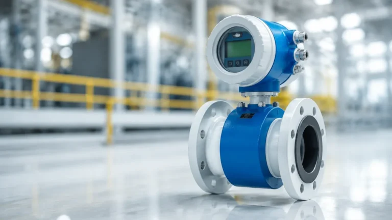
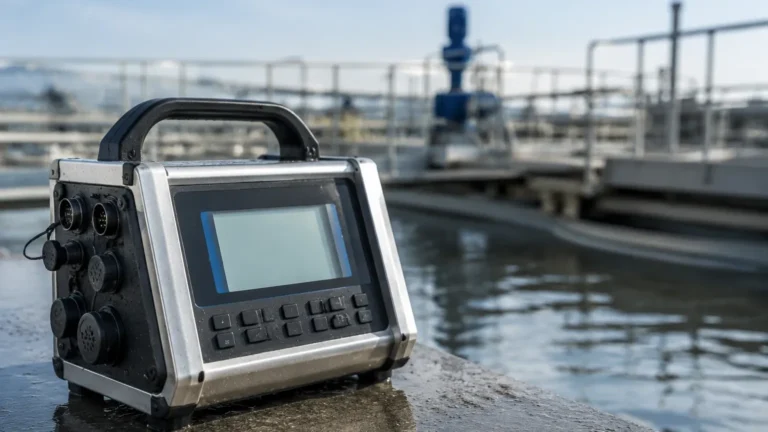
Mass Flow Transmitter
Mass Flow Transmitter
In the realm of industrial process control, the ability to quantify the movement of materials with high precision is fundamental to operational efficiency and safety. While volumetric flow measurement was once the industry standard, the modern demand for accuracy has shifted the focus toward the mass flow transmitter. Unlike volumetric devices, which measure the space a fluid occupies, a mass flow transmitter measures the actual mass of the fluid passing through a system. This distinction is critical because mass remains constant regardless of changes in temperature, pressure, or density, whereas volume does not.
For engineers and plant managers, understanding the nuances of mass flow measurement is essential for optimizing chemical reactions, ensuring precise custody transfer, and maintaining rigorous mass balance across complex systems. This guide explores the principles, selection criteria, and practical applications of mass flow transmitters in contemporary industrial environments.
Measurement Principles of Mass Flow Transmitters
To select the appropriate instrument, one must first understand the physics governing the measurement. Mass flow transmitters primarily utilize two distinct technologies: Coriolis and Thermal.
Coriolis Measurement Principle
Coriolis flowmeters are often considered the "gold standard" for mass flow measurement. They operate based on the Coriolis effect—an inertial force described by Gustave-Gaspard Coriolis in the 19th century.
Inside the transmitter, the fluid flows through one or two vibrating tubes. An internal drive coil causes the tubes to oscillate at their resonant frequency. When fluid enters the vibrating tube, it is forced to take on the vertical momentum of the vibration. As the fluid moves toward the center of the tube, it resists the upward motion, pushing down on the tube. Conversely, as it leaves the center, it resists the decreasing motion, pushing up. This creates a twisting effect (a phase shift) across the tube. The degree of this twist is directly proportional to the mass flow rate.
Because this method measures inertia directly, it is independent of fluid properties such as viscosity and density. Furthermore, the resonant frequency of the tube vibration changes based on the density of the fluid, allowing Coriolis transmitters to provide simultaneous measurements of mass flow, density, and temperature.
Thermal Mass Measurement Principle
Thermal mass flow transmitters are predominantly used for gas applications. They operate on the principle of heat transfer. Typically, the sensor consists of two RTDs (Resistance Temperature Detectors) immersed in the flow stream. One sensor is heated to a specific temperature above the ambient fluid temperature, while the second sensor acts as a reference, measuring the actual process temperature.
As gas flows past the heated sensor, it carries heat away (convective cooling). The transmitter calculates the mass flow by measuring the amount of electrical power required to maintain the constant temperature differential between the two sensors. Since the heat-carrying capacity of a gas is a function of its molecular weight and mass, the cooling effect is directly related to the mass flow of the gas, regardless of pressure or temperature fluctuations.
The Relationship Between Flow and Level Measurement
In many industrial processes, flow measurement and level measurement are two sides of the same coin. While a mass flow transmitter monitors the rate of material moving through a pipe, level measurement instruments—such as the radar and ultrasonic sensors provided by Welk—monitor the total inventory within a vessel.
Integrating these two data points allows for a comprehensive mass balance. For example, in a chemical blending tank, the mass flow transmitter ensures that the exact mass of a reactant is added, while a high-precision level meter provides a secondary verification of the total volume and detects potential leaks or vessel abnormalities. By reviewing the diverse range of level measurement technologies on the Main Page, engineers can design systems that cross-reference flow and level data to achieve higher safety standards and process repeatability.
Key Evaluation Criteria for Selection
Selecting a mass flow transmitter requires a detailed analysis of the process conditions and the specific goals of the application. The following criteria should be evaluated during the procurement phase:
1. Fluid Type and Phase
Coriolis meters are highly versatile and can handle liquids, slurries, and high-pressure gases. However, they may struggle with fluids containing significant entrained air (two-phase flow). Thermal mass transmitters are excellent for clean gases but are generally unsuitable for liquids due to the high power required to maintain temperature differentials in dense media.
2. Required Accuracy and Turndown Ratio
Coriolis transmitters offer exceptional accuracy, often within ±0.1% of the flow rate. They also provide a high turndown ratio (the ratio between maximum and minimum measurable flow), sometimes exceeding 100:1. Thermal transmitters typically offer accuracies around ±1% and are preferred for low-flow gas applications where other technologies might fail to detect movement.
3. Pressure Drop
Coriolis meters, especially those with curved tubes, can introduce a significant pressure drop into the system. In low-pressure gas systems, this may be unacceptable. Thermal mass transmitters are often "insertion" style or have straight-through bores, resulting in negligible pressure loss.
4. Process Conditions
Extreme temperatures and pressures can affect the mechanical integrity of the vibrating tubes in a Coriolis meter. Conversely, thermal meters are sensitive to the composition of the gas; if the gas mixture changes (e.g., a shift in the ratio of Methane to CO2), the thermal conductivity changes, and the meter must be recalibrated.
Practical Selection Table
| Feature | Coriolis Mass Flow | Thermal Mass Flow |
| :— | :— | :— |
| Primary Media | Liquids, Slurries, High-Pressure Gas | Gases, Compressed Air |
| Typical Accuracy | ±0.1% to ±0.2% | ±1.0% to ±2.0% |
| Direct Density Output | Yes | No |
| Pressure Drop | Moderate to High | Very Low |
| Cost Profile | High Initial Investment | Moderate |
| Maintenance | Low (No moving parts) | Low (Periodic cleaning) |
Installation Considerations and Best Practices
A mass flow transmitter is a precision instrument; its performance is heavily dependent on correct installation. Engineers should adhere to the following guidelines to ensure long-term reliability:
* Vibration Isolation: Coriolis meters are sensitive to external mechanical vibrations. They should be mounted using robust supports and, if necessary, flexible couplings to isolate the meter from pump or compressor noise.
* Orientation for Media: For liquid applications, Coriolis meters should ideally be installed with the tubes pointing downward ("flag" or "U" shape down) to prevent gas bubbles from being trapped. For gas applications, the tubes should point upward to prevent condensate accumulation.
* Straight Run Requirements: Thermal mass flow transmitters require significant straight pipe runs (typically 10-20 diameters upstream) to ensure a fully developed flow profile. Coriolis meters are generally immune to flow profile distortions and require little to no straight run.
* Zero Calibration: Upon installation and under full process pressure but zero flow, a "zero-point calibration" must be performed. This accounts for the specific stresses and mounting conditions of the installed pipework.
Common Risks and Limitations
While mass flow transmitters offer superior data, they are not without limitations. The high cost of Coriolis technology can be a barrier for non-critical applications. Furthermore, the physical size and weight of large-bore Coriolis meters require substantial structural support.
For thermal transmitters, the primary risk is moisture or particulate contamination. If liquid droplets hit the heated sensor, they cause a momentary spike in the cooling effect, which the transmitter interprets as a massive surge in flow rate. Proper filtration and knockout pots are essential in wet gas applications.
Frequently Asked Questions (FAQs)
Q: Can a mass flow transmitter replace a volumetric meter and a densitometer?
A: Yes, a Coriolis mass flow transmitter inherently measures both mass and density. In many applications, this single instrument replaces the need for multiple sensors, reducing the number of process penetrations and potential leak points.
Q: How often should a mass flow transmitter be calibrated?
A: Calibration frequency depends on the criticality of the process and the stability of the media. In custody transfer applications, annual calibration is common. For stable, non-corrosive processes, many users rely on internal diagnostics and extend calibration cycles to 3-5 years.
Q: Does pipe size limit the use of mass flow transmitters?
A: Coriolis meters become prohibitively expensive and heavy in sizes above 10 inches (250 mm). In very large pipes, thermal insertion meters or multi-variable differential pressure transmitters are often more practical.
Conclusion
The integration of a mass flow transmitter into an industrial process represents a commitment to precision and data-driven management. By measuring mass directly, facilities can eliminate the variables of temperature and pressure, leading to tighter process control and improved bottom-line results. Whether utilizing the inertial force of a Coriolis meter or the convective cooling of a thermal sensor, selecting the right technology requires a deep understanding of the fluid dynamics at play.
For those managing bulk storage or complex processing tanks, combining these flow insights with reliable level measurement is the key to total system visibility. For more information on selecting the right level instruments to complement your flow strategy, Review product options and application support to find the most accurate solutions for your specific industrial needs.