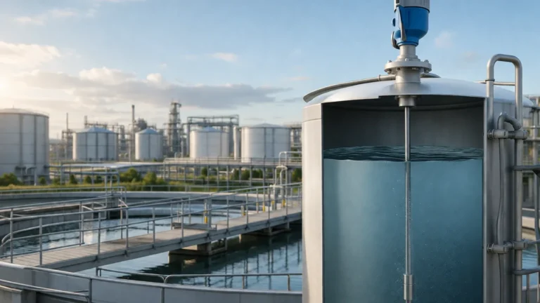
Mass Gas Flow Meter
Mass Gas Flow Meter
In industrial process control and automation, the accurate measurement of gas is a fundamental requirement for safety, efficiency, and fiscal accountability. Unlike liquids, which are largely incompressible, gases change volume significantly with variations in temperature and pressure. Consequently, volumetric flow measurement often requires additional compensation to be meaningful. A mass gas flow meter solves this challenge by measuring the actual mass of the gas molecules passing through a conduit, providing a stable and reliable data point regardless of fluctuating process conditions.
For engineers and plant managers, selecting the right mass gas flow meter requires a deep understanding of the underlying physics, the specific properties of the gas being measured, and the environmental constraints of the installation site. This guide provides a technical overview of mass gas flow measurement technologies, selection criteria, and practical implementation strategies.
Understanding Mass vs. Volumetric Flow
To appreciate the utility of a mass gas flow meter, one must distinguish between actual cubic meters (ACM) and standard or normal cubic meters (SCM/NCM). Volumetric meters, such as vortex or turbine meters, measure the space the gas occupies. If the pressure doubles, the volume halves, even though the amount of gas (the mass) remains the same.
Mass flow measurement is preferred in B2B industrial applications because:
1. Chemical Reactions: Stoichiometric ratios in burners and reactors depend on the mass of the reactants.
2. Custody Transfer: Billing for natural gas or industrial gases (oxygen, nitrogen, argon) is based on the energy content, which correlates directly with mass.
3. Efficiency: Compressed air systems and boiler efficiency monitoring require mass data to identify leaks and optimize fuel-to-air ratios.
Core Measurement Principles of Mass Gas Flow Meters
Two primary technologies dominate the industrial landscape for direct mass gas flow measurement: Thermal Dispersion and Coriolis. Each operates on distinct physical principles and offers specific advantages.
Thermal Dispersion Technology
Thermal mass flow meters operate based on the principle of heat transfer. The sensor typically consists of two Resistance Temperature Detectors (RTDs). One RTD acts as a reference, measuring the ambient temperature of the gas. The second RTD is heated to a specific, constant temperature differential above the reference.
As gas flows past the heated sensor, the gas molecules carry heat away—a process known as convective cooling. The amount of energy required to maintain the temperature differential is directly proportional to the mass flow rate of the gas. This relationship is governed by King’s Law, which relates heat loss to the mass velocity of the fluid. Because this method depends on the heat capacity and thermal conductivity of the gas, the meter must be calibrated for the specific gas composition used in the process.
Coriolis Mass Flow Technology
Coriolis meters provide a direct mass measurement by utilizing the Coriolis effect. The instrument contains one or more vibrating tubes. When gas flows through these vibrating tubes, it induces a phase shift or "twist" in the vibration. The magnitude of this phase shift is directly proportional to the mass flow rate.
While Coriolis meters are highly accurate and independent of gas composition, they are traditionally more expensive and can experience significant pressure drops when used with low-density gases. However, for high-pressure gas applications or where gas composition is variable, they remain the gold standard.
Key Evaluation Criteria for Selection
Choosing a mass gas flow meter involves balancing performance requirements against budget and installation constraints. Consider the following factors:
* Turndown Ratio: This is the ratio between the maximum and minimum measurable flow rates. Thermal mass flow meters often offer excellent turndown ratios (up to 100:1 or higher), making them ideal for detecting leaks in compressed air systems where flow can vary from nearly zero to peak capacity.
* Accuracy and Repeatability: For custody transfer, high accuracy (±0.5% of reading) is required. For process monitoring, ±1% to ±2% may suffice.
* Pressure Drop: In low-pressure systems, the energy loss caused by the meter itself can be a concern. Thermal meters are generally non-intrusive or have low profiles, resulting in minimal pressure drop.
* Gas Composition: If the gas is a mixture (e.g., biogas or flare gas) that changes over time, a thermal meter may require recalibration or a multi-gas capability. A Coriolis meter, conversely, is unaffected by composition changes.
* Response Time: In applications involving fast-acting valves or burner controls, a rapid response time (typically < 1 second) is essential.
Practical Selection Table for Industrial Gases
| Gas Type | Recommended Technology | Primary Benefit | Typical Application |
| :— | :— | :— | :— |
| Compressed Air | Thermal Dispersion | High turndown, low cost | Leak detection, plant air monitoring |
| Natural Gas | Thermal or Coriolis | Direct mass, no compensation | Boiler fuel feed, custody transfer |
| Pure Oxygen/Nitrogen | Thermal Dispersion | High sensitivity, clean | Semiconductor, medical gas |
| Biogas (Wet/Dirty) | Thermal (with coating) | No moving parts | Wastewater treatment, landfills |
| High-Pressure CO2 | Coriolis | Extreme accuracy | Food & Beverage, Carbon capture |
| Flare Gas | Thermal (Insertion) | Wide range, large pipes | Refineries, environmental compliance |
Installation Best Practices and Considerations
Even the most advanced mass gas flow meter will fail to provide accurate data if installed incorrectly. Engineering teams should adhere to the following guidelines:
Straight Pipe Runs
Most flow meters require a fully developed flow profile to measure accurately. This usually necessitates a specific length of straight pipe upstream and downstream of the meter to eliminate turbulence caused by elbows, valves, or reducers.
* Standard Requirement: Typically 10 to 20 diameters (D) upstream and 5D downstream.
* Flow Conditioners: If space is limited, flow conditioners (perforated plates or vane-type) can be used to shorten the required straight run.
Orientation and Positioning
For thermal mass flow meters, the probe must be oriented correctly relative to the flow direction. In horizontal pipes, it is often recommended to install the sensor at the 10 o'clock or 2 o'clock position to avoid moisture accumulation at the bottom or air pockets at the top. For Coriolis meters, vertical installation with upward flow is often preferred to ensure the tubes remain full and to prevent the trapping of condensates.
Gas Condition
Thermal mass flow meters are sensitive to moisture. If water droplets hit the heated sensor, they evaporate and cause a momentary "spike" in the flow reading, as the latent heat of vaporization is much higher than the heat capacity of the gas. In wet gas applications, moisture separators or heated sensors may be necessary.
Limitations and Common Risks in Gas Flow Measurement
While highly effective, mass gas flow meters have specific limitations that must be managed:
1. Coating and Fouling: In dirty gas applications (like coke oven gas), particulates or tars can coat the sensors. This acts as an insulator for thermal meters, leading to under-reporting of flow. Regular cleaning or the use of "self-cleaning" high-power sensors is required.
2. Extreme Velocities: Very high gas velocities can lead to sensor vibration or structural failure in insertion-type meters. Ensure the meter is rated for the maximum possible flow during a process upset.
3. Calibration Mismatch: Since thermal meters are gas-specific, using a meter calibrated for Air on a Helium line will result in massive errors. Always verify the factory calibration against the actual process gas.
Integrating Flow and Level Measurement in Process Systems
In many industrial environments, gas flow measurement is part of a broader mass balance strategy that includes liquid or solid level measurement. For instance, in a chemical reactor, the rate at which gas is consumed (measured by a mass gas flow meter) must be balanced against the level of liquid reactants in the tank.
Reliable level measurement instruments, such as radar or ultrasonic sensors, provide the volume data for the liquid phase, while flow meters provide the rate of change for the gaseous phase. For engineers looking to integrate these systems, it is helpful to Review product options and application support to ensure that both level and flow instruments are compatible with the control architecture (e.g., 4-20mA HART, Modbus, or Profibus).
Frequently Asked Questions (FAQ)
Q: Does a thermal mass gas flow meter require temperature or pressure compensation?
No. By design, the thermal dispersion principle measures mass flow directly. However, some units provide temperature and pressure outputs as secondary variables for process monitoring.
Q: Can I use a mass gas flow meter for steam?
Generally, no. Standard thermal mass flow meters are not suitable for steam due to the high temperatures and the phase-change nature of the fluid. Specialized vortex or differential pressure meters with compensation are typically used for steam.
Q: How often should a mass gas flow meter be calibrated?
This depends on the criticality of the process and the cleanliness of the gas. In clean gas service, many meters can operate for 2–3 years without significant drift. In regulated industries or dirty gas applications, annual calibration or "in-situ" verification is recommended.
Q: What is the difference between an insertion meter and an inline meter?
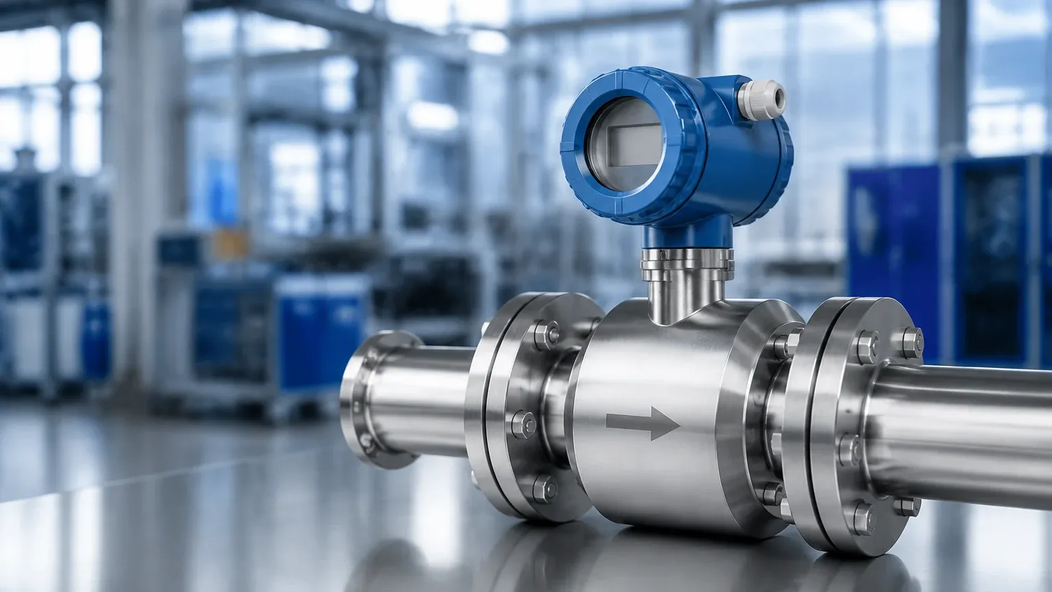
An inline meter is a complete spool piece that is flanged or threaded into the pipe. It is typically used for smaller pipe sizes (under 100 mm). An insertion meter consists of a probe that is inserted through a hole in the pipe wall, making it a cost-effective solution for large diameter ducts and pipes.
Conclusion
The implementation of a mass gas flow meter is a critical step toward achieving precision in industrial gas management. By selecting the appropriate technology—whether the versatile thermal dispersion meter or the highly accurate Coriolis meter—and adhering to strict installation standards, facilities can significantly reduce waste and improve process safety. For comprehensive technical specifications and to explore how these systems integrate with industrial level measurement, visit the Main Page for further engineering resources and product guidance.