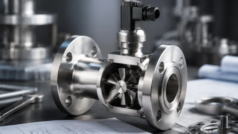
Micropilot Fmr20
Micropilot Fmr20
In the realm of industrial process automation, precise level measurement is a cornerstone of operational efficiency, safety, and inventory management. The Micropilot FMR20 represents a significant evolution in non-contact radar level measurement technology. Designed primarily for the water and wastewater industry, as well as utilities across various sectors, this instrument utilizes high-frequency radar waves to determine the distance to a product surface without making physical contact. This guide explores the technical foundations, application criteria, and installation requirements for the Micropilot FMR20, providing a comprehensive reference for engineers and facility managers.
Measurement Principles of Radar Level Meters
Before evaluating specific hardware like the Micropilot FMR20, it is essential to understand the underlying physics of radar level measurement. Radar sensors operate on the principle of "Time of Flight" (ToF). The device emits high-frequency electromagnetic pulses (typically in the GHz range) toward the medium. These pulses travel at the speed of light, hit the surface of the material, and are reflected back to the sensor’s antenna.
The Time of Flight (ToF) Calculation
The distance ($D$) from the sensor to the material surface is calculated using the formula:
$D = \frac{c \times t}{2}$
Where:
* $c$ is the speed of light ($approx 300,000$ km/s).
* $t$ is the measured transit time of the pulse.
Because the speed of light is constant, the accuracy of the measurement depends on the sensor's ability to precisely time the interval between emission and reception. Modern radar instruments, including the FMR20, use advanced signal processing algorithms to filter out "noise" or false echoes caused by tank internals, turbulence, or foam.
Frequency Modulated Continuous Wave (FMCW) vs. Pulsed Radar
While some radar sensors use short pulses, many high-performance units utilize Frequency Modulated Continuous Wave (FMCW) technology. In FMCW, the sensor emits a continuous signal with a constantly changing frequency. The difference in frequency between the emitted signal and the received echo is directly proportional to the distance. The Micropilot FMR20 specifically leverages 80 GHz technology. Higher frequencies allow for a narrower beam angle, which is critical for avoiding obstructions in narrow tanks or shafts.
Technical Overview of the Micropilot FMR20
The Micropilot FMR20 is categorized as a compact radar sensor. Its design philosophy emphasizes simplicity, reliability, and ease of integration. Unlike traditional radar gauges that may require complex wiring and large housings, the FMR20 is often housed in a fully potted, chemically resistant PVDF (Polyvinylidene fluoride) body, making it suitable for harsh environments.
Key Specifications
* Measuring Range: Typically up to 10 meters (33 feet) or 20 meters (66 feet) depending on the specific model variant.
* Accuracy: $\pm 2$ mm ($0.08$ inches), providing high precision for inventory control.
* Frequency: 80 GHz, which minimizes the beam angle to approximately 8° (with a 40mm antenna).
* Process Temperature: Standard ranges from -40°C to +80°C (-40°F to +176°F).
* Process Pressure: Operates from -1 to 3 bar (-14.5 to 43.5 psi).
* Communication: 4-20mA HART, Modbus RS485, or Bluetooth for wireless commissioning.
For organizations looking to compare these specifications with a broader range of industrial measurement tools, the Main Page of our instrumentation catalog offers detailed comparisons of radar, ultrasonic, and hydrostatic technologies.
Selection Criteria and Application Suitability
Choosing the right level sensor requires an analysis of the medium, the vessel geometry, and environmental conditions. The Micropilot FMR20 is optimized for specific scenarios but may not be the ideal choice for every application.
Practical Selection Table
| Factor | Suitability for FMR20 | Notes |
| :— | :— | :— |
| Medium State | Liquid | Primarily designed for water, wastewater, and chemicals. |
| Surface Turbulence | Moderate | 80 GHz signal processing handles ripples well. |
| Foam Presence | Limited | Heavy, dense foam can absorb radar signals. |
| Tank Geometry | Narrow/Complex | Small beam angle avoids internal obstructions. |
| Corrosive Media | High | PVDF housing provides excellent chemical resistance. |
| Vacuum/High Pressure | Low | Limited to 3 bar; not suitable for high-pressure reactors. |
| Dust/Vapor | High | Radar is largely unaffected by dust or heavy steam. |
When to Choose Radar Over Ultrasonic
While ultrasonic sensors are cost-effective, radar sensors like the FMR20 offer distinct advantages in specific conditions:
1. Temperature Fluctuations: Ultrasonic waves depend on air density, which changes with temperature. Radar waves are electromagnetic and unaffected by air temperature.
2. Vapors and Gases: Heavy vapors can attenuate or deflect ultrasonic signals. Radar penetrates most vapors without loss of accuracy.
3. Vacuum: Ultrasonic sensors require a medium (air) to travel through. Radar works perfectly in a vacuum.
Installation Considerations and Best Practices
Proper installation is the most critical factor in ensuring the long-term reliability of a radar level meter. Even the most advanced signal processing cannot compensate for a poorly positioned sensor.
Positioning the Sensor
1. Avoid the Center: Do not mount the sensor in the exact center of a cylindrical tank. This can lead to multiple reflections (parabolic effect) that interfere with the primary signal.
2. Distance from Wall: The sensor should be mounted at a distance from the wall of at least 1/6th of the tank diameter. This prevents the radar beam from reflecting off the wall or internal build-up.
3. Beam Path Obstructions: Ensure the path of the radar beam is clear of ladders, heating coils, or agitators. While the 80 GHz beam is narrow, any metal object in its path will create a strong false echo.
4. Nozzle Height: If mounting on a nozzle, the antenna should ideally extend slightly beyond the bottom of the nozzle to prevent signal interference from the nozzle edge.
Blocking Distance (Dead Zone)
Every radar sensor has a "blocking distance" (also known as a dead zone) directly below the antenna. For the FMR20, this is typically around 250 mm (approx. 10 inches). Level measurements cannot be taken within this zone. Ensure the sensor is mounted high enough that the maximum liquid level never enters the blocking distance.

Limitations and Environmental Factors
While the Micropilot FMR20 is a versatile tool, engineers must be aware of its factual limitations to avoid project failures.
Dielectric Constant ($ε_r$)
The ability of a material to reflect radar waves depends on its dielectric constant ($ε_r$). Water has a high $ε_r$ (approx. 80) and is an excellent reflector. Hydrocarbons, oils, and some solvents have low $ε_r$ values (often < 2.0). If the $ε_r$ is too low, the signal may pass through the liquid and reflect off the bottom of the tank instead. The FMR20 is generally rated for media with $ε_r \geq 2$, but very low-dielectric fluids may require a stilling well or a guided wave radar (GWR) solution.
Build-up and Condensation
Although the FMR20's PVDF face is designed to shed droplets, extreme condensation or heavy crystalline build-up on the antenna can attenuate the signal. In applications with heavy condensation, ensure the sensor is mounted perfectly vertical to allow moisture to drip off the center of the lens.
Maintenance and Troubleshooting
One of the primary benefits of non-contact radar is the lack of moving parts, which significantly reduces maintenance requirements. However, periodic verification is recommended.
* Signal Strength Monitoring: Most digital interfaces (HART/Bluetooth) allow users to view the "echo curve." A weakening signal over time may indicate build-up on the antenna lens.
* Calibration Verification: Comparing the radar reading against a manual dip-tape measurement is a standard practice for commissioning and annual audits.
* Bluetooth Security: When using the SmartBlue app for commissioning, ensure that security passwords are set and documented to prevent unauthorized configuration changes.
Frequently Asked Questions (FAQs)
Q: Can the Micropilot FMR20 be used in outdoor open-channel flow applications?
A: Yes. When paired with a suitable transmitter or PLC that can perform the necessary math (V-notch weir or Flume calculations), the FMR20 is an excellent choice for open-channel flow due to its weather resistance and high accuracy.
Q: Does the sensor require a clear line of sight?
A: Yes. Radar is a line-of-sight technology. While it can penetrate some non-conductive materials (like plastic tank lids), any metal or conductive obstruction will block the signal.
Q: Is the FMR20 suitable for explosive atmospheres?
A: The FMR20 is available with various global certifications (ATEX, IECEx, CSA) for use in hazardous areas. Always check the specific nameplate and documentation for the Ex-rating of your specific unit.
Q: How does the 80 GHz frequency help in small tanks?
A: Higher frequency allows for a smaller antenna to produce a narrower beam. A 26 GHz radar might have a 20° beam angle, while the 80 GHz FMR20 has an 8° beam. This allows the sensor to "see" between obstructions in cramped spaces without interference.
Conclusion
The Micropilot FMR20 stands as a robust, entry-level radar solution that brings high-end 80 GHz technology to standard water and utility applications. By understanding the principles of radar propagation and adhering to strict installation guidelines regarding beam angles and dielectric properties, engineers can achieve highly reliable level monitoring with minimal maintenance. For further technical support or to explore alternative measurement technologies such as ultrasonic or hydrostatic transmitters, please refer to our Main Page for a full suite of industrial solutions.