Non Contact Level Sensors
Non Contact Level Sensors
In the landscape of industrial process control, the ability to accurately monitor the volume of liquids and solids within a vessel is critical for operational efficiency, safety, and inventory management. Traditional contact-based measurement methods, while effective in many scenarios, often face significant challenges when dealing with corrosive chemicals, viscous fluids, or hygienic requirements. Non contact level sensors have emerged as the preferred solution for these demanding environments, providing a reliable means of measurement without physical interaction with the media.
By eliminating contact, these sensors reduce the risk of mechanical failure, contamination, and chemical degradation. This guide explores the underlying principles of non-contact technologies, provides a framework for selection, and outlines the practical engineering considerations necessary for successful implementation.
Understanding Measurement Principles
Non contact level sensors primarily utilize two physical phenomena to determine the distance from the sensor face to the surface of the material: sound waves (ultrasonic) and electromagnetic waves (radar). Both technologies operate on the Time-of-Flight (ToF) principle, though their interaction with the environment differs significantly.
Ultrasonic Level Measurement
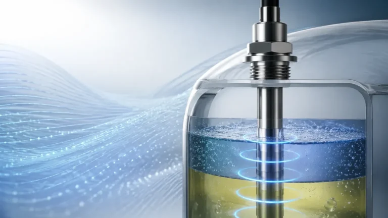
Ultrasonic sensors function by emitting high-frequency sound pulses, typically in the range of 20 kHz to 200 kHz. These pulses travel through the air or gas space above the material, reflect off the surface, and return to the sensor's transducer, which acts as both a transmitter and a receiver.
The distance ($D$) is calculated using the formula:
$D = (v \times t) / 2$
Where:
* $v$ is the speed of sound in the medium (typically air).
* $t$ is the total time elapsed between transmission and reception.
Because the speed of sound is highly dependent on the temperature of the air (varying approximately 0.17% per degree Celsius), most industrial ultrasonic sensors include integrated temperature compensation. However, they are sensitive to changes in gas composition and cannot operate in a vacuum, as sound requires a medium to propagate.
Radar Level Measurement
Radar sensors utilize high-frequency electromagnetic waves, often operating in the C-band (approx. 6 GHz), K-band (24-26 GHz), or W-band (76-81 GHz). Unlike sound, radar waves travel at the speed of light and are largely unaffected by air temperature, pressure, or vacuum conditions.
There are two primary radar methodologies:
1. Pulse Radar: The sensor sends out a short microwave pulse and measures the time it takes to return. This is similar to the ultrasonic method but at much higher speeds.
2. Frequency Modulated Continuous Wave (FMCW): The sensor emits a continuous signal with a constantly changing frequency. The difference in frequency between the transmitted signal and the reflected signal (the "beat frequency") is proportional to the distance. FMCW radar generally offers higher accuracy and better signal-to-noise ratios than pulse radar, making it ideal for complex industrial tanks.
Comparative Analysis: Ultrasonic vs. Radar
Choosing between ultrasonic and radar technologies requires an understanding of the process environment. The following table summarizes the key differences to assist in the selection of non contact level sensors.
| Feature | Ultrasonic Sensors | Radar (FMCW/Pulse) |
| :— | :— | :— |
| Medium of Propagation | Sound waves (requires air/gas) | Electromagnetic waves (works in vacuum) |
| Typical Range | 0.25m to 15m (0.8ft to 49ft) | 0.1m to 100m (0.3ft to 328ft) |
| Accuracy | ±0.25% of range | ±1mm to ±5mm (±0.04" to ±0.2") |
| Effect of Temperature | High (requires compensation) | Negligible |
| Effect of Pressure | Limited to ~3 bar (43.5 psi) | Up to 160 bar (2320 psi) or more |
| Effect of Dust/Vapor | Significant attenuation | Minimal impact (frequency dependent) |
| Cost | Lower | Higher |
| Ideal Applications | Water treatment, open channels | Chemical reactors, oil tanks, solids silos |
For a comprehensive look at specific hardware configurations and technical specifications, engineers can Review product options and application support at the Welk main page.
Key Selection Criteria for Industrial Applications
Selecting the appropriate sensor involves more than just choosing between radar and ultrasonic. Engineers must evaluate the specific characteristics of the vessel and the material being measured.
1. Dielectric Constant (εr)
For radar sensors, the reflectivity of the material is determined by its dielectric constant. Materials with high dielectric constants (e.g., water, $\epsilon_r \approx 80$) reflect radar waves very well. Non-conductive materials like oils or plastic pellets have low dielectric constants ($\epsilon_r < 3$), which result in weaker return signals. In these cases, high-frequency radar (80 GHz) or specialized signal processing is required.
2. Surface Conditions
Turbulent surfaces, foam, and heavy agitation can scatter the sensor's signal. Ultrasonic waves are particularly susceptible to absorption by heavy foam, which can lead to a "lost echo" condition. Radar can often penetrate light foam, but dense, conductive foam may still present a challenge. If the surface is consistently turbulent, sensors with advanced damping algorithms or the use of a stilling well may be necessary.
3. Vessel Geometry and Internal Obstructions
Internal structures such as ladders, heating coils, and agitator blades can create "false echoes." When selecting a sensor, the beam angle is a critical specification. A narrower beam angle (common in high-frequency radar) allows the sensor to avoid these obstructions. For ultrasonic sensors, the beam is typically wider, requiring more careful placement to ensure a clear path to the material surface.
Installation Best Practices and Geometric Considerations
Proper installation is the single most important factor in ensuring the long-term reliability of non contact level sensors. Even the most advanced sensor will fail to provide accurate data if mounted incorrectly.
Mounting Position
* Avoid the Center: In cylindrical tanks, mounting the sensor in the exact center can lead to multiple reflections (parabolic effect) that confuse the sensor. It is generally recommended to mount the sensor at 1/2 to 1/3 of the tank radius from the wall.
* Stay Away from the Wall: Mounting too close to the tank wall can cause interference from weld seams or build-up on the wall. A minimum distance of 200mm to 500mm (8" to 20") is typically required, depending on the beam angle.
* Inflow Interference: Never mount a sensor directly above the fill stream. The falling material will obstruct the signal and provide a false high-level reading.
The "Dead Zone" or Blocking Distance
Every non-contact sensor has a minimum distance it cannot measure, known as the dead zone or blocking distance. For ultrasonic sensors, this is the time required for the transducer to stop vibrating after transmission before it can begin listening. For radar, it is the area where the signal is too close to the antenna to be processed accurately. If the material level enters this zone, the reading will become erratic or lock at the maximum value. Engineers must ensure the sensor is mounted high enough (perhaps using a nozzle extension) so that the maximum expected level never enters this dead zone.
Nozzle Design
If the sensor is mounted on a pipe nozzle, the nozzle must be smooth and free of burrs. For radar, the nozzle should be as short as possible. If the nozzle is long, the radar beam might reflect off the nozzle walls before even entering the tank, creating a large parasitic echo at the top of the measurement range.

Environmental Limitations and Mitigation
While non contact level sensors are robust, certain environmental factors can impede their performance. Understanding these limitations allows for the implementation of mitigation strategies.
* Condensation and Build-up: In high-humidity applications, condensation can form on the sensor face. While many sensors are designed to shed droplets, heavy build-up can block the signal. Sensors with PTFE-faced antennas or integrated air purge systems can help maintain a clear signal path.
* Vapor and Gas Layers: Ultrasonic sensors are heavily affected by heavy vapors (like gasoline or solvents) because these vapors change the speed of sound. If the vapor concentration changes, the level reading will drift. Radar is the preferred choice in these environments as electromagnetic waves are not affected by gas composition.
* Extreme Temperatures: While the sensor electronics are often rated for -40°C to +80°C (-40°F to 176°F), the process temperature can be much higher. Remote-mounted electronics or specialized cooling fins/thermal isolators are used to protect the sensor head from extreme process heat.
Frequently Asked Questions (FAQ)
Q: Can non-contact sensors measure solids like powders or grains?
A: Yes. Both ultrasonic and radar sensors are used for solids. However, solids often have an angle of repose (a sloped surface) rather than a flat one, which scatters the signal. Radar, particularly 80 GHz high-frequency radar, is generally superior for solids because its narrow beam can be aimed more precisely and it handles dust better than ultrasonic sensors.
Q: How do I handle a tank with an agitator?
A: Most modern non-contact sensors include a "false echo suppression" or "background subtraction" feature. During commissioning, the engineer can map the tank while it is empty and the agitator is running. The sensor records the fixed reflections from the agitator and subtracts them from the live measurement. Additionally, using a sensor with a fast update rate ensures the level is tracked between agitator blade passes.
Q: Is it possible to measure through a plastic tank wall?
A: Radar sensors can often see through non-conductive plastic or fiberglass tank walls. This allows for "non-invasive" measurement where the sensor is mounted entirely outside the tank, looking through the roof. This is ideal for highly aggressive chemicals where even the sensor housing would be at risk. Ultrasonic sensors cannot do this, as the sound waves would reflect off the plastic wall rather than passing through it.
Q: What maintenance is required for non-contact sensors?
A: One of the primary advantages of these sensors is low maintenance. Because there are no moving parts and no contact with the media, there is no wear. Periodic inspection of the sensor face for significant build-up or cleaning of the antenna is usually all that is required. If the sensor is equipped with self-diagnostics, it can often alert the control system if the signal strength is degrading due to build-up.
Conclusion
Non contact level sensors represent a significant advancement in process instrumentation, offering a combination of precision and durability that contact-based methods struggle to match. By understanding the physical principles of ultrasonic and radar technologies—and carefully considering the geometric and environmental constraints of the application—engineers can implement measurement solutions that reduce downtime and improve process safety. For those seeking to integrate these technologies into their operations, the Main Page provides access to a wide range of industrial-grade instruments designed for the most challenging environments.