Power Plant Power Generation Flow Meters
Power Plant Power Generation Flow Meters
In the complex environment of a modern utility, the accuracy and reliability of power plant power generation flow meters are fundamental to operational efficiency, safety, and regulatory compliance. These instruments measure the movement of various fluids—including high-pressure steam, treated feedwater, cooling water, and fuel—across the Rankine cycle and auxiliary systems. Because power generation involves extreme temperatures and pressures, selecting the correct flow measurement technology requires a deep understanding of fluid dynamics and instrument physics.
While flow measurement tracks the volume or mass of moving fluids, it is often inextricably linked to level measurement. For instance, maintaining the water-steam interface in a boiler drum requires precise data from both feedwater flow meters and high-accuracy level sensors. Manufacturers like Welk provide the essential level measurement instruments that complement flow data to ensure stable plant operations. For a comprehensive overview of industrial measurement technologies, you can visit the Main Page.
Core Measurement Principles for Power Plant Environments
Before selecting a specific instrument, engineers must evaluate the underlying physical principle of the meter. In power generation, the most common principles include differential pressure, velocity-based measurement, and mass flow measurement.
Differential Pressure (DP)
Differential pressure remains the most widely used principle in power plants. It relies on Bernoulli’s equation, which states that as the velocity of a fluid increases, its pressure decreases. By placing a primary element—such as an orifice plate, Venturi tube, or flow nozzle—in the pipe, a pressure drop is created. The square root of this pressure difference is proportional to the flow rate.
* Orifice Plates: Simple and cost-effective but cause significant permanent pressure loss.
* Flow Nozzles: Preferred for high-velocity steam and feedwater due to their erosion resistance and better pressure recovery compared to orifice plates.
* Venturi Tubes: Offer the lowest permanent pressure loss and are ideal for large-diameter cooling water lines.
Ultrasonic (Transit-Time)
Transit-time ultrasonic meters use acoustic signals to measure fluid velocity. Transducers are mounted on the exterior or interior of the pipe. Signals sent upstream and downstream travel at different speeds relative to the ground; the time difference is used to calculate velocity. These are highly valued in power plants for their non-invasive nature, particularly in retrofitting cooling water systems where cutting into large-diameter pipes is cost-prohibitive.
Vortex Shedding
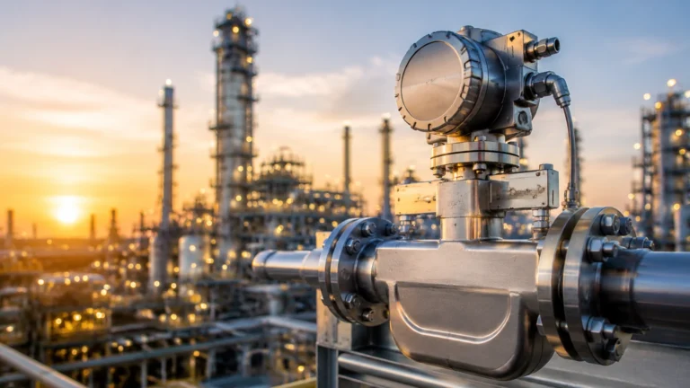
Vortex meters operate on the von Kármán effect. As fluid flows past a bluff body (a non-streamlined object) placed in the flow stream, vortices are shed alternately on either side. The frequency of this shedding is directly proportional to the fluid's velocity. These meters are robust, have no moving parts, and are excellent for measuring saturated or superheated steam.
Electromagnetic (Magmeters)
Magmeters apply Faraday’s Law of Induction. As a conductive liquid (like raw cooling water) flows through a magnetic field, it generates a voltage proportional to its velocity. These meters provide an unobstructed flow path and are immune to changes in fluid density and viscosity, though they cannot measure non-conductive fluids like demineralized water or steam.
Key Applications Across the Power Cycle
Boiler Feedwater and Condensate
Feedwater measurement is critical for maintaining the mass balance of the boiler. These systems operate at high pressures (often exceeding 15 MPa / 2175 PSI) and temperatures (up to 250°C / 482°F). Flow nozzles are the standard here due to their durability. Accurate feedwater flow data is essential for the "three-element control" strategy, which balances steam flow, feedwater flow, and drum level to prevent boiler damage.
Main Steam and Reheat Steam
Measuring the flow of superheated steam (typically at 540°C / 1004°F) is one of the harshest applications for power plant power generation flow meters. Vortex meters or specialized DP elements (like Annubars or high-temperature nozzles) are used. Precise steam measurement allows the plant to calculate the heat rate, a primary metric for fuel efficiency.
Cooling Water Systems
Power plants require vast amounts of water to condense steam back into liquid. Large-diameter pipes (often >1000 mm) carry this water. Because of the scale, even small inaccuracies can lead to significant energy waste in pumping. Electromagnetic meters or clamp-on ultrasonic meters are preferred for these low-pressure, high-volume applications.
Fuel Flow (Gas and Oil)
For gas-fired or oil-fired plants, fuel flow measurement directly impacts billing and emissions reporting. Coriolis meters are frequently used for fuel oil because they measure mass flow directly, compensating for temperature-driven density changes. For natural gas, ultrasonic or thermal mass flow meters are common.
Selection Criteria for Power Plant Power Generation Flow Meters
Choosing the right meter involves balancing technical requirements with lifecycle costs. The following table summarizes the suitability of different technologies for common power plant fluids.
| Technology | Fluid Type | Typical Accuracy | Pressure Drop | Maintenance Level |
| :— | :— | :— | :— | :— |
| Orifice Plate (DP) | Steam, Water, Gas | 1.0% – 2.0% | High | Medium |
| Flow Nozzle (DP) | High-Velocity Steam | 0.5% – 1.5% | Medium | Low |
| Vortex | Steam, Gas, Water | 0.75% – 1.0% | Low | Low |
| Ultrasonic | Clean Water | 0.5% – 1.0% | None | Low |
| Electromagnetic | Cooling Water | 0.25% – 0.5% | None | Very Low |
| Coriolis | Fuel Oil, Chemical | 0.1% – 0.2% | Medium | Low |
Critical Evaluation Factors
1. Turndown Ratio: This is the ratio of the maximum to minimum flow the meter can accurately measure. Power plants that "cycle" (change load frequently) require meters with high turndown (e.g., 10:1 or 20:1) to remain accurate during low-load periods.
2. Process Conditions: Verify that the wetted materials can withstand the pH levels of treated water and the erosive nature of high-velocity steam.
3. Accuracy vs. Repeatability: In many control loops, repeatability (the ability to provide the same result under the same conditions) is more important than absolute accuracy.

Installation and Engineering Considerations
The performance of power plant power generation flow meters is heavily dependent on proper installation. Even the most expensive meter will fail to provide accurate data if installed incorrectly.
Straight Pipe Requirements
Most flow meters require a certain length of straight pipe upstream and downstream to eliminate turbulence caused by elbows, valves, or pumps.
* DP Meters: Typically require 10 to 20 diameters upstream.
* Vortex Meters: Often require 15 to 25 diameters upstream.
* Ultrasonic: Requirements vary but generally need 10 diameters.
If straight runs are unavailable, flow conditioners (vane or perforated plate types) must be installed.
Orientation and Fluid State
For liquid applications, the pipe must always be full. In horizontal runs, sensors for DP meters should be mounted on the side of the pipe to prevent air bubbles (in liquid lines) or condensate (in gas lines) from entering the impulse piping. For steam, the impulse lines must be sloped and equipped with condensate pots to protect the transmitter from high temperatures.
Integration with Level Systems
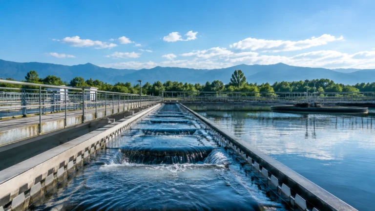
In applications like open-channel cooling water discharge, flow is often calculated by measuring the level of water passing over a weir or through a flume. In these cases, ultrasonic or radar level transmitters, such as those manufactured by Welk, are used to determine the head height, which is then converted to a flow rate using standard hydraulic formulas.
Limitations and Challenges
Despite advances in technology, several factors can compromise flow measurement in power plants:
* Cavitation and Flashing: In condensate systems, if the pressure drops below the vapor pressure, bubbles form (cavitation), which can damage the meter and cause massive errors in ultrasonic and DP readings.
* Scaling and Fouling: Cooling water, especially from rivers or sea sources, can lead to mineral buildup or biological growth inside the meter, shifting the calibration.
* Vibration: Power plants are high-vibration environments. Vortex meters, which rely on frequency detection, can sometimes misinterpret pipe vibration as flow, leading to "false flows" at zero velocity.
* Signal Interference: In electromagnetic meters, proximity to large motors or high-voltage lines can introduce electrical noise into the signal.
Frequently Asked Questions (FAQ)
Q: How often should power plant flow meters be calibrated?
A: Most plants follow a 12-to-24-month calibration cycle for critical billing or safety meters. However, meters used for general process monitoring may only require "zero-checks" or verification against a master meter every 3 to 5 years.
Q: Can I use a clamp-on ultrasonic meter for high-pressure steam?
A: Generally, no. While clamp-on technology exists for some steam applications, the high temperatures and the acoustic properties of steam make it extremely difficult. In-line vortex or DP meters are the industry standard for steam.
Q: What is the benefit of using a multivariable transmitter with a DP meter?
A: A multivariable transmitter measures differential pressure, static pressure, and temperature simultaneously. It uses this data to calculate real-time density, providing a compensated mass flow reading, which is essential for accurate steam and gas measurement.
Q: How do I measure flow in partially filled pipes?
A: Standard flow meters require a full pipe. For partially filled pipes (common in wastewater or discharge), you must use an area-velocity meter or combine a level sensor with a flume or weir structure.
By integrating robust flow measurement with reliable level instrumentation, power plant operators can achieve the precision necessary for modern grid demands. For further technical specifications on level measurement components that support these systems, consult the Main Page.