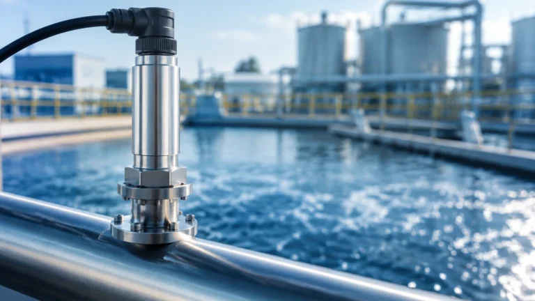
Pressure Flow Meter
Pressure Flow Meter
In the landscape of industrial process control, the pressure flow meter remains one of the most widely utilized and trusted technologies for measuring the movement of liquids, gases, and steam. Often referred to as differential pressure (DP) flow meters, these instruments rely on well-established physical laws to convert a change in pressure into a highly accurate flow rate measurement. For engineers and facility managers, understanding the nuances of these devices is essential for optimizing system efficiency and ensuring the longevity of industrial assets.
As a professional manufacturer of industrial measurement instruments, Welk provides a broad spectrum of solutions ranging from radar and ultrasonic sensors to specialized pressure-based systems. This guide explores the engineering principles, selection criteria, and practical applications of the pressure flow meter within modern industrial frameworks.
Fundamental Principles of Pressure Flow Meters
The operation of a pressure flow meter is based on Bernoulli’s principle, which states that as the speed of a moving fluid increases, the pressure within the fluid decreases. In a closed pipe, this is achieved by introducing a deliberate constriction or obstruction in the flow path.
When a fluid passes through this constriction, its velocity increases, resulting in a localized drop in static pressure. By measuring the difference between the high-pressure zone (upstream of the constriction) and the low-pressure zone (at or just after the constriction), the flow rate can be calculated. The relationship is defined by the square root law: the flow rate (Q) is proportional to the square root of the differential pressure (ΔP).
Mathematically, this is expressed as:
**Q = k * √ΔP**
Where:
* Q is the volumetric or mass flow rate.
* k is a discharge coefficient determined by the geometry of the meter and fluid properties.
* ΔP is the differential pressure measured by the transmitter.
Because the relationship is non-linear, modern digital transmitters are required to perform a "square root extraction" to provide a linear output (such as a 4-20mA signal) that corresponds directly to the flow rate.
Common Types of Primary Flow Elements
The "primary element" is the physical component that creates the pressure drop. Choosing the right primary element is the most critical step in specifying a pressure flow meter for a specific application.
Orifice Plates
The orifice plate is the most common primary element due to its simplicity and cost-effectiveness. It consists of a thin metal plate with a precisely machined hole (orifice) in the center, clamped between two pipe flanges.
* Advantages: Low cost, easy to install, and well-documented standards (ISO 5167).
* Disadvantages: High permanent pressure loss and susceptibility to wear or clogging if the fluid contains solids.
Venturi Tubes
Venturi tubes feature a tapered inlet and a diverging outlet. This aerodynamic shape allows for a significant pressure drop with very low permanent pressure loss.
* Advantages: Excellent for high-velocity flows and fluids with suspended solids; requires shorter straight pipe runs than orifice plates.
* Disadvantages: Higher initial cost and larger physical footprint.
Pitot Tubes and Annubars
Pitot tubes measure the difference between static pressure and impact (dynamic) pressure at a specific point in the flow stream. Annubars are averaging Pitot tubes that use multiple sensing points across the pipe diameter to provide a more representative flow profile.
* Advantages: Minimal pressure drop and easy installation (often via a single hot-tap).
* Disadvantages: Sensitive to flow profile distortions and not suitable for low-velocity applications.
Flow Nozzles
Flow nozzles are essentially a cross between an orifice plate and a Venturi tube. They are designed with a curved inlet that leads to a cylindrical throat.
* Advantages: Highly resistant to erosion, making them ideal for high-temperature and high-velocity steam applications.
Engineering Selection Criteria for Industrial Applications
Selecting a pressure flow meter requires a detailed analysis of the process conditions. Engineers should evaluate the following criteria before finalizing a specification:
| Criteria | Orifice Plate | Venturi Tube | Pitot/Annubar |
| :— | :— | :— | :— |
| Accuracy | ±0.5% to ±2% | ±0.5% to ±1.5% | ±1% to ±2% |
| Pressure Loss | High | Low | Very Low |
| Relative Cost | Low | High | Medium |
| Fluid Type | Clean liquids/gases | Slurries/Dirty fluids | Clean liquids/gases |
| Installation | Flanged | Inline/Welded | Insertion |
| Maintenance | Medium (Edge wear) | Low | Low (Clogging risk) |
Fluid Properties
The viscosity, density, and temperature of the medium significantly impact the Reynolds number, which in turn affects the accuracy of the pressure flow meter. For instance, highly viscous fluids may require specialized orifice designs (like quadrant edge orifices) to maintain a predictable discharge coefficient.
Turndown Ratio
One limitation of DP-based flow measurement is the turndown ratio, typically limited to 3:1 or 4:1 in basic systems due to the square root relationship. If the flow rate drops to 10% of the maximum, the differential pressure drops to only 1% of the maximum, which may fall below the sensitivity threshold of the transmitter. High-performance transmitters can extend this range significantly.
Installation Best Practices and Impulse Line Configuration
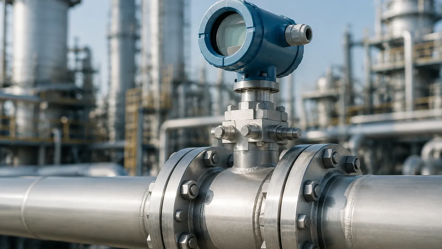
The accuracy of a pressure flow meter is heavily dependent on the installation environment. Even the highest quality transmitter will provide erroneous data if the primary element is installed incorrectly.
1. Straight Pipe Runs: To ensure a fully developed flow profile, primary elements require a specific length of straight pipe upstream and downstream. A general rule of thumb is 10D (diameters) upstream and 5D downstream, though this varies based on the presence of elbows or valves.
2. Impulse Line Orientation: The small tubes connecting the primary element to the transmitter (impulse lines) must be oriented correctly to prevent trapped air or sediment.
* For Liquids: The transmitter should be mounted below the pipe to allow air bubbles to rise back into the process line.
* For Gases: The transmitter should be mounted above the pipe to allow condensate to drain back into the process line.
3. Manifold Valves: A three-valve or five-valve manifold should always be used. This allows the transmitter to be zeroed under process pressure and isolated for maintenance without shutting down the main line.
Limitations and Operational Risks
While the pressure flow meter is a robust tool, it is not without risks. Engineers must account for the following during the design phase:
* Permanent Pressure Loss (PPL): Unlike ultrasonic or magnetic flow meters, DP meters extract energy from the process to create the pressure drop. In high-volume pumping systems, the energy cost associated with PPL over several years can exceed the initial cost of a more expensive, low-loss meter like a Venturi.
* Orifice Wear: In abrasive applications, the sharp edge of an orifice plate can become rounded over time. This changes the discharge coefficient and leads to a gradual under-measurement of flow.
* Impulse Line Freezing: In cold climates, impulse lines containing liquid can freeze, leading to sensor damage or false readings. Heat tracing or insulation is often required.
Synergy Between Flow and Level Measurement Technologies
In many industrial settings, pressure-based measurement serves a dual purpose. The same differential pressure transmitters used in a pressure flow meter setup are frequently employed for hydrostatic level measurement in pressurized tanks.
By measuring the pressure at the bottom of a vessel and subtracting the gas-space pressure at the top, the transmitter determines the liquid head pressure, which is directly proportional to the level. This technological overlap allows plants to standardize their spare parts inventory and training protocols. For a comprehensive overview of industrial measurement technologies, including radar, ultrasonic, and hydrostatic options, engineers can visit the Main Page of our technical resource center to review product options and application support.
Frequently Asked Questions (FAQ)
Q: Can a pressure flow meter measure bi-directional flow?
A: Standard orifice plates and Venturi tubes are unidirectional. However, specialized bi-directional orifice plates and symmetrical primary elements exist, though they require a transmitter capable of processing both positive and negative differential pressures.
Q: How often should an orifice plate be inspected?
A: This depends entirely on the fluid. For clean water, an annual inspection may suffice. For steam or abrasive slurries, quarterly inspections are recommended to check for edge sharpness and flatness.
Q: What is the impact of changing fluid density on the measurement?
A: Since the flow calculation relies on fluid density, any significant change in temperature or pressure (especially in gases) will introduce errors. In these cases, a "compensated" flow measurement is required, using additional sensors for temperature and static pressure to adjust the flow calculation in real-time.
Q: Are pressure flow meters suitable for very small pipe sizes?
A: Yes, integral orifice meters are designed specifically for small pipes (typically below 50 mm or 2 inches). These units combine the primary element and the transmitter into a single assembly to minimize installation errors.
Conclusion and Project Confirmation
Before proceeding with the procurement of a pressure flow meter, project teams should confirm several key data points to ensure the selected instrument meets the application requirements:
1. Full Scale Flow Rate: Define the minimum, normal, and maximum expected flow rates.
2. Process Conditions: Confirm the maximum operating pressure and temperature, as well as the fluid's density and viscosity at those conditions.
3. Pipe Specifications: Provide the exact internal diameter (ID) and material of the piping, as the Beta ratio (the ratio of the orifice diameter to the pipe diameter) is critical for accuracy.
4. Allowable Pressure Drop: Determine the maximum permissible permanent pressure loss the system can tolerate.
By following these guidelines and leveraging the technical expertise available at Welk, industrial operators can implement flow measurement solutions that provide reliable data for years of continuous operation. Whether your application requires the simplicity of a pressure flow meter or the advanced capabilities of radar level sensing, selecting the right tool for the environment is the cornerstone of process excellence.