Pressure Measurement Device
Pressure Measurement Device
In the landscape of industrial automation and process control, the pressure measurement device stands as one of the most versatile and essential instruments. While pressure sensing is a fundamental requirement for monitoring pipe flow and vessel safety, it is also a primary method for determining liquid level through hydrostatic principles. For engineers and plant managers, selecting the correct pressure measurement device requires a deep understanding of fluid mechanics, sensor metallurgy, and the specific environmental demands of the application.
This guide explores the engineering principles behind pressure-based level measurement, the various hardware configurations available, and the critical selection criteria used in water treatment, chemical processing, and oil and gas industries.
Fundamental Principles of Pressure-Based Level Measurement
The use of a pressure measurement device to determine liquid level relies on the principle of hydrostatic pressure. This principle states that the pressure exerted by a static liquid column at a specific point is directly proportional to the height of the liquid above that point, provided the density of the fluid remains constant.
The Hydrostatic Equation
The relationship is defined by the formula:
P = ρ × g × h
Where:
* P is the hydrostatic pressure (typically measured in Pascals or bar).
* ρ (rho) is the density of the liquid (kg/m³).
* g is the acceleration due to gravity (approximately 9.81 m/s²).
* h is the height of the liquid column (meters).
In practical industrial applications, because gravity is constant and the density of the process fluid is usually known, the pressure measurement device can be calibrated to output a level reading in meters or millimeters. For example, in a water tank (density ≈ 1000 kg/m³), every 1 meter of depth exerts approximately 0.098 bar (9.8 kPa) of pressure.
Atmospheric vs. Sealed Systems
There are two primary ways a pressure measurement device handles ambient conditions:
1. Gauge Pressure: In vented or open-to-atmosphere tanks, the sensor must compensate for changes in atmospheric pressure. This is usually achieved via a small vent tube within the sensor cable that allows the back of the sensing diaphragm to "breathe" against the current barometric pressure.
2. Differential Pressure (DP): In pressurized or vacuum-sealed vessels, a single pressure sensor cannot determine level because the internal gas pressure adds to the hydrostatic pressure. In these cases, a differential pressure measurement device is used to subtract the head pressure from the total pressure at the bottom, leaving only the value of the liquid column.
Types of Pressure Measurement Devices for Level Control
Industrial applications utilize several distinct hardware architectures depending on the mounting requirements and the nature of the fluid.
1. Submersible Level Transmitters
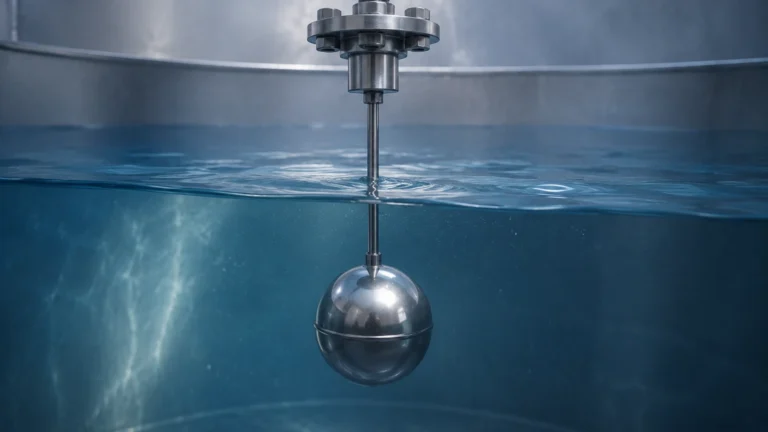
These are specialized pressure measurement devices designed to be lowered directly into the liquid. The sensor is housed in a waterproof casing (usually 316L stainless steel or titanium) and is suspended by a reinforced cable that contains the signal wires and an atmospheric vent tube. These are common in deep wells, reservoirs, and wastewater lift stations.
2. Externally Mounted Pressure Transmitters
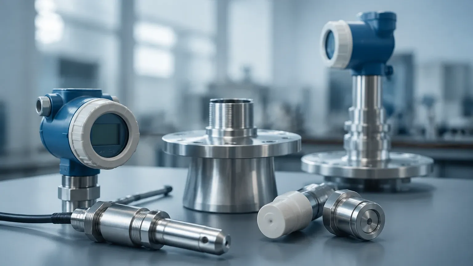
For tanks with bottom or side-wall nozzles, a standard pressure transmitter can be threaded or flanged into place. The sensing diaphragm is in direct contact with the fluid at the bottom of the tank. This configuration is easier to maintain as the sensor can be isolated with a block valve without entering the tank.
3. Differential Pressure (DP) Transmitters
As mentioned, DP cells are the standard for pressurized boilers or chemical reactors. They feature two ports: a high-pressure port connected to the bottom of the vessel and a low-pressure port connected to the vapor space at the top. The device calculates the difference between the two, providing an accurate level reading regardless of the internal tank pressure.
Technical Selection Criteria
Choosing a pressure measurement device involves balancing accuracy requirements against the harshness of the process media. The following table provides a comparison of common configurations:
| Feature | Submersible Transmitters | Externally Mounted (Gauge) | Differential Pressure (DP) |
| :— | :— | :— | :— |
| Primary Application | Deep wells, open reservoirs | Vented storage tanks | Pressurized vessels, boilers |
| Installation | Suspended by cable | Flanged or NPT threaded | Dual-port piping/capillaries |
| Typical Accuracy | 0.25% to 0.5% FS | 0.1% to 0.25% FS | 0.075% to 0.1% FS |
| Maintenance | High (must pull cable) | Low (isolation valves) | Moderate (impulse line checks) |
| Media Compatibility | Water, wastewater, fuel | Chemicals, oils, slurries | Corrosive gases and liquids |
| Max Temperature | Usually < 80°C | Up to 120°C (standard) | Up to 400°C (with seals) |
Installation and Engineering Considerations
To ensure the longevity and accuracy of a pressure measurement device, several installation factors must be addressed during the design phase.
Turbulence and Physical Protection
In tanks with high-speed agitators or heavy inflow, a submersible sensor may swing, leading to physical damage or erratic readings. In these environments, engineers should install a "stilling well"—a perforated pipe that surrounds the sensor to dampen fluid movement while allowing the pressure to equalize.
Cable Venting and Moisture
For submersible units, the vent tube is the most common point of failure. If moisture enters the vent tube, it can block the atmospheric reference or cause internal corrosion. Using a desiccant cartridge at the termination box is a standard best practice to keep the vent tube dry.
Diaphragm Material Selection
The sensing diaphragm is often very thin (0.05 mm to 0.1 mm) to remain sensitive to small pressure changes. In chemical applications, 316L stainless steel may not be sufficient. Options such as Tantalum, Hastelloy C, or ceramic diaphragms are necessary for handling acids or highly abrasive slurries.
Mounting Location
The device should be mounted away from the immediate vicinity of pump intakes or discharge pipes. The localized pressure drops or surges (Bernoulli effect) near moving fluid can cause the pressure measurement device to report a "false" level that does not reflect the actual static head of the tank.
Limitations and Potential Risks
While hydrostatic pressure measurement is reliable and cost-effective, it is not a "fit and forget" solution for every application. Engineers must be aware of the following limitations:
1. Density Sensitivity: Because the device measures weight (pressure), any change in the liquid's density will result in a level error. If a tank is used to store different chemicals at different times, or if the temperature fluctuates significantly (changing the density), the transmitter must be recalibrated or compensated via a PLC.
2. Sediment Buildup: In wastewater or mining applications, silt and sludge can accumulate at the bottom of the tank. If the sensor diaphragm becomes covered in solids, the pressure reading will become sluggish or drift significantly.
3. Mechanical Shock: Pressure sensors are sensitive to "water hammer"—sudden pressure spikes caused by the rapid closing of valves. These spikes can permanently deform the diaphragm, leading to a shifted zero point or total sensor failure.
Frequently Asked Questions (FAQ)
Q: Can a pressure measurement device be used for liquids with foam?
A: Yes. One of the primary advantages of hydrostatic pressure over ultrasonic or radar methods is that it is unaffected by surface foam. The sensor measures the mass of the liquid column, ignoring the light, airy foam on top.
Q: How often should a pressure-based level sensor be calibrated?
A: For most industrial applications, an annual calibration check is recommended. However, in high-temperature or corrosive environments, semi-annual checks may be necessary to account for diaphragm fatigue or material drift.
Q: What is the difference between a pressure transducer and a pressure transmitter?
A: While the terms are often used interchangeably, a *transducer* typically outputs a raw voltage (e.g., 0-100mV), whereas a *transmitter* includes signal conditioning electronics to provide an industry-standard output like 4-20mA, HART, or Modbus RS485.
Q: Is it possible to measure the level of a boiling liquid?
A: It is challenging. Boiling changes the effective density of the fluid by introducing gas bubbles into the liquid column. This lower density will cause the pressure measurement device to report a level lower than the actual physical height. In these cases, differential pressure with remote seals is often required.
Conclusion and Next Steps
The pressure measurement device remains a cornerstone of industrial level sensing due to its simplicity and lack of moving parts. By understanding the relationship between fluid density and head pressure, and by selecting materials compatible with the process media, facilities can achieve highly accurate and repeatable measurements.
When evaluating hardware for a specific project, it is essential to consult with a professional manufacturer to ensure the sensor's range and chemical resistance align with your operational goals. For a comprehensive look at available sensing technologies, including radar and ultrasonic alternatives, you may Review product options and application support on the Welk Main Page. Selecting the right instrument today prevents costly downtime and maintenance challenges in the future.