Pressure Transducer
Pressure Transducer
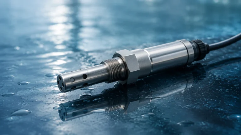
In the landscape of industrial automation and process control, the pressure transducer serves as a fundamental component for monitoring and managing fluid dynamics. While often associated with simple pressure readings in pipelines, its application in hydrostatic level measurement is one of the most reliable methods used in modern engineering. By converting mechanical force into a measurable electrical signal, these instruments allow operators to determine the precise level of liquids in tanks, wells, and reservoirs.
This article examines the technical principles, selection criteria, and practical installation requirements for utilizing a pressure transducer in level measurement applications. Understanding these factors is essential for engineers and procurement professionals seeking to optimize system accuracy and longevity.
Measurement Principles of Hydrostatic Level Sensing
The use of a pressure transducer for level measurement is based on the principle of hydrostatics. This principle states that the pressure exerted by a static liquid column is directly proportional to its height, the density of the liquid, and the force of gravity.
The Hydrostatic Equation
The fundamental formula used in these calculations is:
P = ρ × g × h
Where:
* P is the hydrostatic pressure (measured in Pascals or bar).
* ρ (rho) is the density of the liquid (kg/m³).
* g is the local acceleration due to gravity (approximately 9.81 m/s²).
* h is the height of the liquid column (meters).
Because gravity is constant and the density of most liquids is known, the pressure transducer can calculate the height (h) by measuring the pressure (P). For example, in a water tank (density ≈ 1000 kg/m³), every 1 meter of water column exerts approximately 9.81 kPa (0.098 bar) of pressure at the base.
Sensing Technologies
Industrial pressure transducers typically employ one of two primary sensing technologies to detect these minute changes in force:
1. Piezoresistive Sensors: These utilize a silicon or metal diaphragm with strain gauges diffused into the surface. When pressure is applied, the diaphragm deforms, changing the electrical resistance of the gauges. This change is processed into a standard signal. Piezoresistive sensors are highly sensitive and ideal for clean water and general industrial applications.
2. Ceramic Capacitive Sensors: These consist of a ceramic base and a movable ceramic diaphragm forming a capacitor. Pressure changes the distance between the plates, altering the capacitance. Ceramic sensors are exceptionally robust, offering high resistance to abrasion and chemical corrosion, making them suitable for wastewater or aggressive chemicals.
Pressure Reference Types
Selecting the correct reference type is critical for accuracy:
* Gauge Pressure: The sensor is vented to the atmosphere via a tube in the cable or a vent on the housing. This compensates for changes in barometric pressure, ensuring that the reading only reflects the liquid height.
* Absolute Pressure: The sensor is sealed against a vacuum. This is rarely used for level unless the atmospheric pressure is measured separately and subtracted via software.
* Differential Pressure (DP): Used in closed or pressurized tanks. Two sensors (or one sensor with two ports) measure the pressure at the bottom and the pressure in the vapor space above the liquid. The difference between the two represents the true liquid level.
Types of Pressure Transducers for Level Measurement
Depending on the tank geometry and the nature of the medium, different physical configurations of the pressure transducer are required.
Submersible Level Transmitters
These are designed to be lowered directly into the liquid. The sensor is housed in a waterproof (IP68) casing, usually made of stainless steel or plastic, and is suspended by a specialized cable. This cable contains the electrical wires and a small capillary tube for atmospheric pressure compensation. These are widely used in deep wells, boreholes, and large open reservoirs.
Externally Mounted Transducers
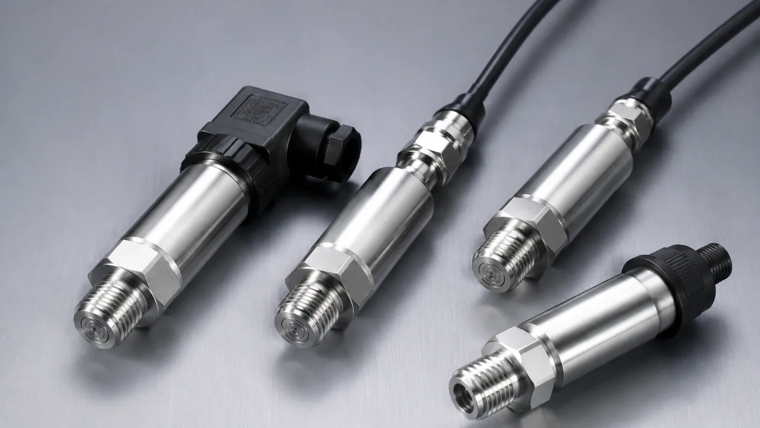
For tanks with existing process connections, a pressure transducer can be mounted to a nozzle at the bottom of the vessel. These typically use threaded (NPT/G) or flanged connections. Because the sensor is outside the tank, maintenance is often easier, provided there is a shut-off valve to isolate the sensor from the process.
Flush Diaphragm Transducers
In applications involving viscous liquids, food products, or slurries that might clog a standard pressure port, a flush diaphragm is used. The sensing element sits flush with the process connection, preventing the buildup of solids and allowing for Clean-in-Place (CIP) procedures.
Key Evaluation Criteria for Selection
Selecting a pressure transducer requires a thorough analysis of the process environment. Failure to account for chemical compatibility or pressure ranges can lead to premature sensor failure or inaccurate data.
1. Material Compatibility
The wetted parts—those in direct contact with the liquid—must be resistant to corrosion.
* 316L Stainless Steel: The standard for water and mild chemicals.
* Hastelloy C / Tantalum: Required for highly corrosive acids or seawater.
* Ceramic: Excellent for abrasive slurries.
* FKM/EPDM Seals: Ensure the O-rings are compatible with the fluid temperature and chemistry.
2. Pressure Range and Overpressure
The transducer should be rated for a range slightly higher than the maximum expected liquid level to ensure safety. However, selecting a range that is too high will reduce the resolution of the measurement. It is also vital to check the "overpressure rating," which indicates the maximum pressure the sensor can withstand without permanent damage or calibration shift.
3. Signal Output and Communication
* 4-20mA Analog: The industry standard for long-distance transmission with high noise immunity.
* 0-10V: Common in HVAC and simple PLC systems.
* HART Protocol: Allows for digital communication over the analog wire, providing diagnostic data and remote calibration.
* RS485/Modbus: Ideal for digital integration in complex automation networks.
4. Accuracy and Stability
Accuracy is usually expressed as a percentage of Full Scale (FS). For critical inventory management, a high-accuracy sensor (e.g., ±0.1% FS) may be necessary. For simple pump control, ±0.5% FS is often sufficient. Long-term stability is also a factor, as it determines how often the sensor requires re-calibration.
Selection Table: Pressure Transducer Comparison
| Feature | Submersible Transducer | Threaded/External Transducer | Differential Pressure (DP) |
| :— | :— | :— | :— |
| Best Use Case | Deep wells, open reservoirs | Small tanks, process piping | Pressurized/Closed vessels |
| Installation | Suspended by cable | Threaded into tank wall | Dual-port connection |
| Maintenance | Easy to lift out | Requires isolation valve | Complex manifold required |
| Max Depth | Up to 200m+ | Limited by tank height | High static pressure capability |
| Atmospheric Comp. | Via vented cable | Via internal vent | Automatic (differential) |
Installation Considerations and Best Practices
Even the highest quality pressure transducer will fail if installed incorrectly. Engineers must follow specific guidelines to ensure reliable operation.
Mounting Location
The sensor should be located away from areas of high turbulence, such as near an inlet pipe or an agitator. If turbulence is unavoidable, a stilling well (a perforated pipe) should be used to shield the sensor from lateral forces and rapid fluctuations.
Cable Management for Submersible Units
The vented cable is the most vulnerable part of a submersible installation. It must not be kinked or crushed, as this will block the atmospheric vent tube. If the cable ends in an outdoor junction box, a desiccant filter or a specialized vent bellows should be installed to prevent moisture from entering the tube and causing internal corrosion or measurement drift.
Lightning and Surge Protection
In outdoor applications like water towers or reservoirs, pressure transducers are susceptible to lightning strikes. Using sensors with built-in surge protection and ensuring the system is properly grounded is essential for protecting the electronics.
Zero Calibration
Upon installation, it is standard practice to perform a zero-point calibration. This accounts for the specific atmospheric conditions and the exact mounting height of the sensor relative to the tank bottom.
Limitations and Practical Constraints
While versatile, the pressure transducer has specific limitations that must be addressed during the engineering phase.
* Density Sensitivity: Since the measurement is based on weight, any change in liquid density will cause a level error. For example, if a tank is calibrated for water but then filled with oil, the level reading will be incorrect unless the density constant is updated in the controller.
* Temperature Effects: Significant temperature changes can affect both the density of the liquid and the electronics of the sensor. High-quality transducers include internal temperature compensation to mitigate this.
* Vapor Space Pressure: In closed tanks, the pressure above the liquid adds to the hydrostatic pressure at the bottom. Without a differential pressure setup or a secondary top-side sensor, a standard pressure transducer cannot provide an accurate level.
* Sedimentation: In tanks containing heavy solids, sediment can settle on the diaphragm of a bottom-mounted sensor, leading to false readings or mechanical damage.
Frequently Asked Questions (FAQ)
Q: How often should a pressure transducer be calibrated?
A: Most industrial sensors should be checked annually. However, in critical applications or harsh environments, semi-annual checks are recommended to ensure the zero point has not drifted.
Q: Can a pressure transducer measure the level of foaming liquids?
A: Yes. One of the primary advantages of hydrostatic measurement over ultrasonic or radar methods is that it is unaffected by foam. The sensor measures the weight of the liquid, ignoring the light, airy foam on top.
Q: What happens if the vent tube in the cable gets blocked?
A: If the vent tube is blocked, the sensor can no longer compensate for barometric pressure changes. This can result in an error of several centimeters of water level as weather systems move through the area.
Q: Is it possible to use a pressure transducer for boiling liquids?
A: It is challenging. Boiling liquids have fluctuating densities due to vapor bubbles, and the high temperature may exceed the sensor's operating limits. In these cases, a diaphragm seal with a capillary tube is often used to isolate the electronics from the heat.
Conclusion and Next Steps
The pressure transducer remains a cornerstone of industrial level measurement due to its simplicity and reliability. By understanding the relationship between pressure, density, and height, and by carefully selecting materials and installation methods, process engineers can achieve highly accurate results in a wide variety of environments.
For those looking to implement these solutions in professional water treatment, chemical processing, or industrial automation, it is important to consult with a manufacturer that offers a broad range of technologies. To explore specific sensor models, technical datasheets, and customized OEM options, you may Review product options and application support on our Main Page. Selecting the right instrument today ensures the safety and efficiency of your operations for years to come.