Open Channel Flow Meter
Open Channel Flow Meter
In industrial and municipal water management, measuring the volume of liquid moving through non-pressurized conduits is a fundamental requirement. An open channel flow meter is a system designed to measure the flow rate of liquids in channels, pipes, or flumes where the top surface of the liquid is exposed to the atmosphere. Unlike closed-pipe systems that rely on pressure differentials or electromagnetic induction, open channel measurement typically utilizes the relationship between the liquid level and the velocity of the flow within a specific geometry.
Effective flow monitoring is critical for regulatory compliance in wastewater discharge, billing in irrigation systems, and process control in industrial plants. This guide examines the technical principles, primary and secondary measurement devices, and the engineering considerations necessary for selecting and installing an open channel flow meter system.
Measurement Principles of Open Channel Flow
Before selecting hardware, it is essential to understand the two primary methods used to calculate flow in open channels: the Level-to-Flow method and the Area-Velocity method.
The Level-to-Flow Principle
This is the most common method used in industrial applications. It relies on the installation of a primary device—such as a weir or a flume—that restricts the flow in a predictable way. By creating a known hydraulic structure, the flow rate ($Q$) becomes a function of the liquid level ($H$) upstream of the restriction.
The general mathematical relationship follows the power law equation:
$Q = K \times H^n$
Where:
* $Q$: Flow rate
* $K$: A constant depending on the dimensions of the primary device
* $H$: The measured head (liquid level)
* $n$: An exponent that varies based on the type of weir or flume (e.g., 1.5 for rectangular weirs, 2.5 for V-notch weirs)
The Area-Velocity Principle
In applications where a primary device cannot be installed (such as large natural rivers or existing sewer lines where head loss must be avoided), the area-velocity method is used. This requires two measurements: the liquid level (to calculate the cross-sectional area of the flow) and the average velocity of the liquid. The flow rate is calculated as:
$Q = A \times V$
Where $A$ is the cross-sectional area and $V$ is the mean velocity. This method often utilizes submerged ultrasonic Doppler sensors or non-contact radar velocity sensors.
Primary Devices: Weirs and Flumes
A primary device is a hydraulic structure that produces a known relationship between level and flow. Choosing the right structure is the first step in designing an accurate monitoring station.
Weirs
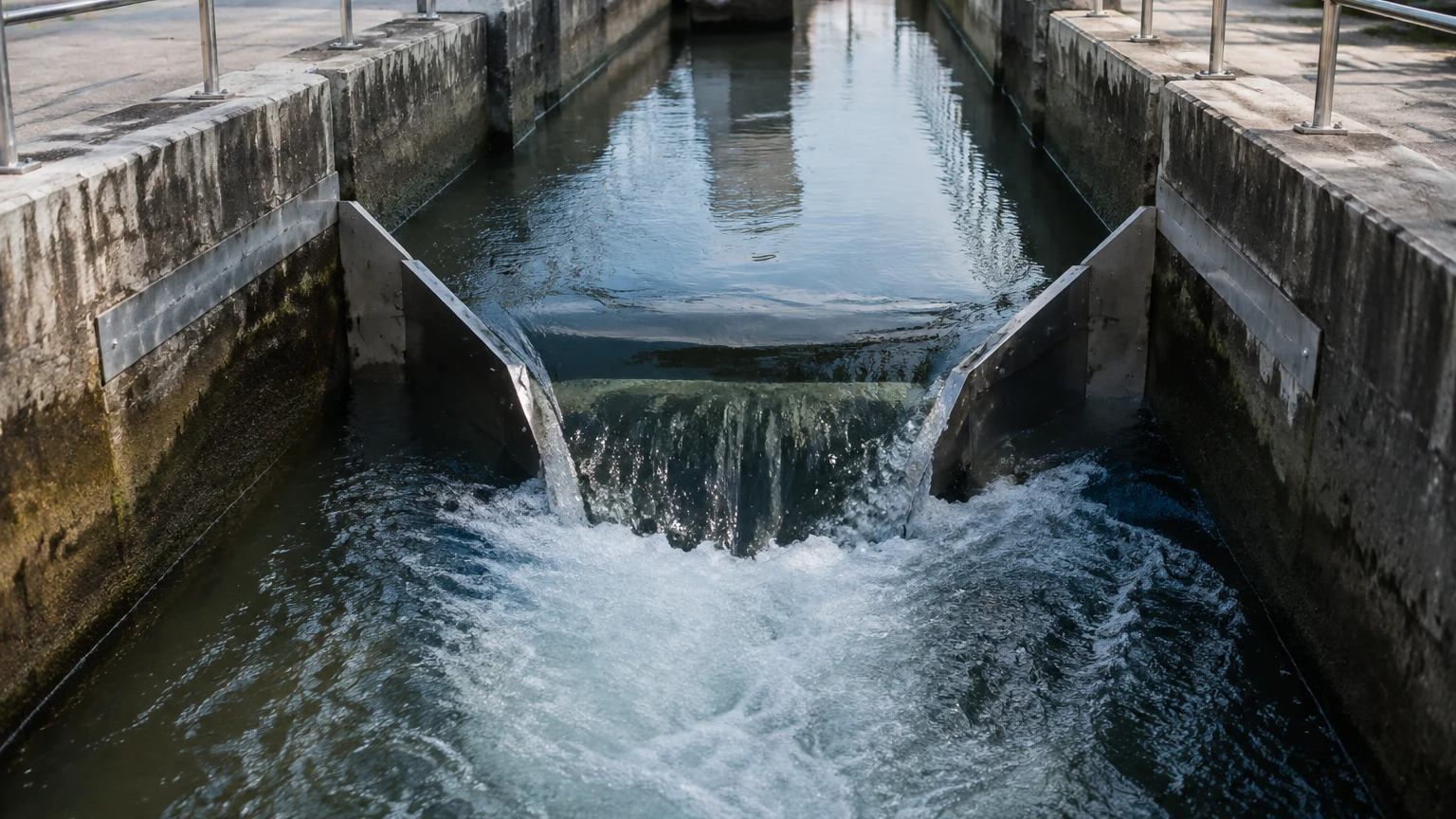
A weir is essentially a dam or obstruction placed across the channel. The liquid flows over the weir crest, and the level is measured upstream.
* V-Notch Weirs (90°, 60°, 45°, 22.5°): Best for low flow rates. They provide high accuracy at low heads because the cross-sectional area of the flow changes significantly with small changes in height.
* Rectangular Weirs: Used for higher flow rates. They can be "suppressed" (spanning the full width of the channel) or "contracted" (narrower than the channel).
* Cipolletti Weirs: A trapezoidal weir that simplifies flow calculations by compensating for end contractions.
Flumes
Flumes are shaped transitions in a channel that constrict the flow area and/or change the slope. They are generally preferred over weirs for liquids containing solids (like raw sewage) because they are self-cleaning.
* Parshall Flumes: The most widely used flume globally. It is highly accurate and handles a wide range of flow rates, though it requires precise installation and a specific drop in the floor.
* Palmer-Bowlus Flumes: Designed to be installed into existing circular pipes or U-shaped channels. They are easier to retrofit than Parshall flumes.
* Khafagi-Venturi Flumes: Commonly used in international industrial wastewater applications due to their low head loss requirements.
Secondary Measurement Instruments
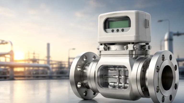
While the primary device creates the conditions for measurement, the secondary device—the flow meter—is responsible for sensing the level and performing the mathematical conversion to flow units.
Ultrasonic Level Sensors
Non-contact ultrasonic sensors are the industry standard for open channel flow. The sensor emits sound pulses that reflect off the liquid surface. By measuring the time-of-flight, the meter determines the distance to the liquid and, consequently, the liquid level.
* Pros: No contact with the medium, low maintenance, cost-effective.
* Cons: Can be affected by heavy foam, steam, or extreme air temperature fluctuations.
Radar Level Meters
Radar sensors use high-frequency microwave pulses instead of sound waves.
* Pros: Unaffected by air temperature, steam, or wind. Ideal for outdoor installations or chemical channels where vapors are present.
* Cons: Higher initial cost than ultrasonic sensors.
Hydrostatic Pressure Transmitters
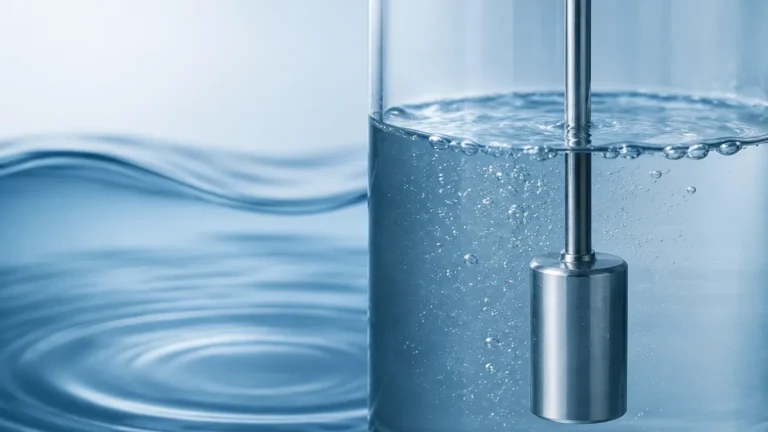
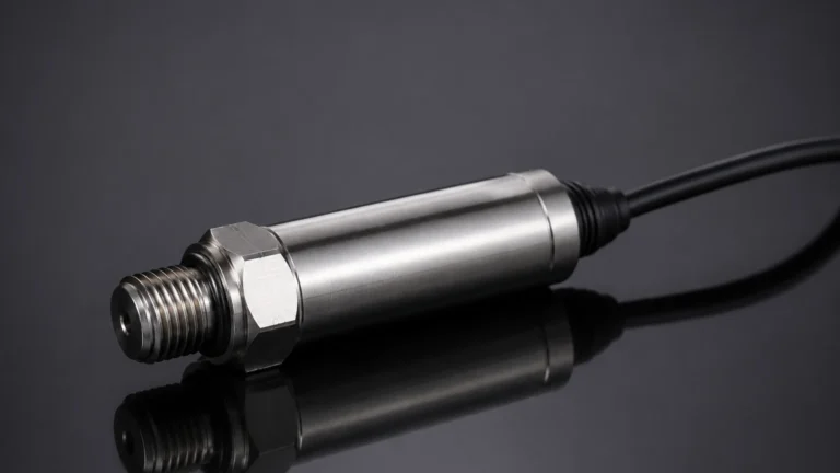
These sensors are submerged at the bottom of the channel or flume and measure the pressure exerted by the liquid column above them.
* Pros: Unaffected by surface foam or turbulence.
* Cons: Contact with the liquid means they are susceptible to fouling, corrosion, or damage from debris.
Selection Criteria for Open Channel Flow Systems
Selecting the appropriate combination of primary and secondary devices depends on the specific application environment. Use the following table as a general reference for selection.
| Criteria | V-Notch Weir | Parshall Flume | Palmer-Bowlus Flume | Area-Velocity Meter |
| :— | :— | :— | :— | :— |
| Best Application | Clean water, low flow | Wastewater, high flow | Retrofit in pipes | Large rivers, no flume possible |
| Solids Handling | Poor (solids settle) | Excellent (self-cleaning) | Good | Moderate |
| Head Loss | High | Low | Moderate | Negligible |
| Installation Ease | Moderate | Difficult (requires civil work) | Easy (insert type) | Easy to Moderate |
| Accuracy | High (±2-3%) | Moderate (±3-5%) | Moderate (±3-5%) | Variable (±5-10%) |
Installation Considerations and Best Practices
Even the most advanced open channel flow meter will fail to provide accurate data if the installation does not follow hydraulic principles. Engineers should confirm the following before commissioning:
1. Upstream Straight Run: For weirs and flumes, the upstream channel should be straight and free of turbulence for at least 5 to 10 times the channel width. This ensures a laminar flow profile.
2. The "H" Point: The level sensor must be installed at a specific distance upstream from the weir or flume throat. For a Parshall flume, this is typically 2/3 of the length of the converging section.
3. Leveling: The primary device must be perfectly level across its width and along its length (unless the specific flume design requires a slope). A tilted weir will result in asymmetrical flow and significant errors.
4. Submergence: Ensure that the downstream conditions do not cause "backwater" or submergence. If the downstream level rises too high, it restricts the flow through the primary device, invalidating the standard level-to-flow equations.
5. Sensor Dead Band: Ultrasonic sensors have a "dead band" (typically 200 mm to 500 mm / 7.8 in to 19.6 in) where they cannot measure. The sensor must be mounted high enough so that even at maximum flow, the liquid level does not enter this zone.
Limitations and Common Risks
* Foam and Turbulence: Thick foam on the surface of the liquid can absorb ultrasonic signals, leading to "lost echo" errors. In such cases, radar or hydrostatic sensors are preferred.
* Siltation: In weir installations, heavy solids can settle behind the weir plate, changing the channel geometry and decreasing accuracy over time.
* Environmental Factors: For outdoor ultrasonic sensors, direct sunlight can heat the sensor face, causing an integrated temperature compensation circuit to provide false readings. Sunshields are highly recommended.
* Chemical Compatibility: When measuring industrial effluent, ensure the sensor materials (PP, PVDF, or Stainless Steel) are compatible with the chemicals present in the waste stream.
Frequently Asked Questions (FAQs)
Q: How often should an open channel flow meter be calibrated?
A: While the electronics of the meter rarely drift, the physical installation should be inspected every 6 to 12 months. This includes checking for debris in the flume, verifying the zero-level setting, and ensuring the sensor remains perpendicular to the liquid surface.
Q: Can I use an open channel flow meter in a partially filled pipe?
A: Yes, provided the pipe is not under pressure and has a free air surface. Palmer-Bowlus flumes or area-velocity sensors are specifically designed for this application.
Q: What is the maximum flow rate these systems can handle?
A: The capacity is determined by the size of the primary device. Large Parshall flumes can measure flow rates exceeding 3,000 m³/h (approx. 13,000 GPM), while small V-notch weirs are suitable for flows as low as 1 m³/h.
Conclusion
Implementing an accurate open channel flow meter system requires a holistic approach that considers the hydraulic characteristics of the site, the nature of the fluid, and the capabilities of the sensing technology. By correctly pairing a primary hydraulic structure with a reliable secondary level sensor, operators can achieve high-precision flow monitoring for years of service. For technical specifications and to explore various sensor technologies for your specific application, you may visit the Main Page to review product options and application support provided by professional instrumentation manufacturers.