Primary Flow Signal
Primary Flow Signal
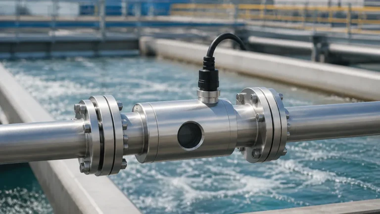
In the realm of industrial process control, the primary flow signal is the fundamental physical manifestation of fluid movement captured by a sensing element. It serves as the bridge between the kinetic energy of a moving fluid—whether liquid, gas, or steam—and the electronic data required by control systems. For engineers and plant managers, understanding the nature of this signal is critical for ensuring accuracy, repeatability, and long-term reliability in process monitoring.
While many industrial facilities focus on the secondary instrument, such as a differential pressure transmitter or a flow computer, the integrity of the measurement begins with the primary flow signal. If the signal generated at the source is noisy, non-linear, or weakened by improper installation, even the most advanced Main Page instrumentation cannot fully compensate for the loss of data quality.
Measurement Principles and Signal Generation
The generation of a primary flow signal typically relies on one of several physical principles. The most common method in heavy industry involves creating a deliberate restriction in the flow path to produce a differential pressure (DP).
The Bernoulli Principle
According to Bernoulli’s equation, as the velocity of a fluid increases, its static pressure decreases. By placing a primary element—such as an orifice plate or a Venturi tube—inside a pipe, the fluid is forced to accelerate through a smaller area. This creates a high-pressure zone upstream and a low-pressure zone downstream. The difference between these two pressures is the primary flow signal. In this configuration, the flow rate (Q) is proportional to the square root of the differential pressure ($ΔP$).
Electromagnetic Induction
For conductive liquids, the primary flow signal is generated via Faraday’s Law of Induction. As a conductive fluid moves through a magnetic field generated by the flow meter, it induces a voltage. This voltage is the primary signal, which is directly proportional to the velocity of the fluid. Unlike DP-based signals, this is a linear relationship, making it easier to process across wide flow ranges.
Frequency and Pulse Generation
In vortex shedding or turbine meters, the primary flow signal is a frequency. As fluid passes a bluff body, it creates alternating vortices (the Von Kármán vortex street). The frequency at which these vortices are shed is the signal. Similarly, in turbine meters, the rotational speed of the blades generates a pulse frequency that corresponds to the volumetric flow rate.
Common Types of Primary Flow Elements
Selecting the right hardware to generate the primary flow signal depends on the fluid properties, pipe size, and the allowable pressure drop. The table below provides a comparison of the most widely used primary elements for DP-based signaling.
Selection Table: Primary Flow Elements
| Element Type | Signal Strength | Permanent Pressure Loss | Accuracy (Typical) | Best Application |
| :— | :— | :— | :— | :— |
| Orifice Plate | High | High (40-90% of ΔP) | ±0.5% to ±2% | Clean liquids, gases, and steam; low cost. |
| Venturi Tube | Moderate | Low (10-20% of ΔP) | ±0.5% to ±1% | High-flow, slurry-laden, or high-pressure fluids. |
| Flow Nozzle | Moderate | Medium (40-60% of ΔP) | ±1% | High-velocity steam and erosive fluids. |
| Pitot Tube | Low | Very Low (<1% of ΔP) | ±1% to ±5% | Large ducts, air flow, and temporary testing. |
| Wedge Meter | Moderate | Medium | ±2% | Highly viscous fluids and abrasive slurries. |
Criteria for Evaluating Signal Quality
When evaluating a primary flow signal, engineers must look beyond simple flow rates. Several technical criteria determine whether a signal is "healthy" enough for stable process control.
1. Signal-to-Noise Ratio: In applications involving turbulent flow or pump pulsations, the primary signal may contain significant "noise." High-quality primary elements are designed to minimize turbulence at the sensing ports to ensure a stable output.
2. Turndown Ratio (Rangeability): This refers to the ratio between the maximum and minimum flow that the element can accurately measure. For a standard orifice plate, the turndown is typically 3:1 or 4:1 because the primary flow signal (DP) drops off rapidly as flow decreases.
3. Repeatability: In many B2B industrial applications, the ability of the primary element to produce the exact same signal under the same conditions is more important than absolute accuracy. This is vital for batching and chemical dosing.
4. Linearity: While DP signals are non-linear (square root), electromagnetic and ultrasonic signals are generally linear. Linear signals provide better accuracy at the lower end of the measurement scale.
Installation Considerations for Signal Integrity
The physical installation of the primary element is the single most common source of signal error. To ensure a reliable primary flow signal, the following engineering guidelines must be followed:
Straight Pipe Requirements
Fluid flow must be fully developed and laminar before it hits the primary element. Obstructions like elbows, valves, and pumps create swirls and velocity profile distortions. Typically, a minimum of 10 to 20 diameters (D) of straight pipe upstream and 5D downstream are required. For example, in a 100 mm (4-inch) pipe, you would need at least 1,000 mm to 2,000 mm of straight pipe before the sensor.
Impulse Line Management
In DP-based systems, the primary flow signal is transmitted from the pipe to the transmitter via impulse lines. These lines must be:
* Sloped: To allow air bubbles to escape (in liquid service) or condensate to drain (in gas service). A slope of at least 1:12 is recommended.
* Short: To minimize signal lag and potential for leaks.
* Equal Temperature: Both lines should be kept at the same temperature to prevent density differences that could bias the pressure signal.
* Properly Tapped: For liquids, taps should be on the side of the pipe to avoid sediment at the bottom and air at the top. For gases, taps should be at the top.

Limitations and Common Risks
Despite their robustness, primary flow signal generators are susceptible to environmental and process-related degradation.
* Erosion and Wear: In abrasive applications, the sharp edge of an orifice plate can become rounded over time. This changes the discharge coefficient and causes the primary flow signal to under-report the actual flow. Regular inspection of the primary element is mandatory in mining or wastewater applications.
* Clogging and Coating: Fluids with high solids content or those prone to crystallization can clog the sensing ports (taps) or coat the internal surfaces of the element. This effectively "muffles" the signal, leading to drift or total signal loss.
* Cavitation and Flashing: If the pressure drop across the primary element is too great, the liquid may vaporize (flash) or form bubbles that collapse (cavitation). This creates extreme signal noise and can physically destroy the primary element and the downstream piping.
Frequently Asked Questions (FAQ)
Q: Can a primary flow signal be used for level measurement?
A: Indirectly, yes. The same differential pressure technology used to generate a flow signal is often applied in hydrostatic level measurement. Many of the sensors found on the Main Page utilize DP principles to calculate the height of a liquid column based on the pressure signal at the bottom of a tank.
Q: How often should a primary flow element be calibrated?
A: Technically, primary elements like orifice plates or Venturi tubes are "geometric" devices; their signal is based on their physical dimensions. Calibration usually involves inspecting the dimensions for wear. The secondary instrument (the transmitter) should be calibrated annually, while the primary element should be inspected every 2 to 5 years depending on the fluid's corrosivity.
Q: What is the difference between a primary and secondary flow element?
A: The primary element is the hardware in contact with the fluid that creates the physical change (e.g., the orifice plate). The secondary element is the device that reads that change and converts it into an electrical signal, such as a 4-20mA or HART output.
Q: Why is my flow signal fluctuating even when the pump speed is constant?
A: This is often due to "signal noise" caused by being too close to a pipe elbow or a partially closed valve. It can also be caused by air trapped in liquid impulse lines or moisture trapped in gas impulse lines.
Conclusion and Technical Confirmation
Before finalizing a specification for a primary flow signal system, project stakeholders should confirm the Reynolds number of the process fluid at minimum and maximum flow rates. This ensures the chosen primary element operates within its predictable range. Additionally, verifying the material compatibility of the element with the process medium is essential to prevent premature failure.
For complex applications involving high-viscosity liquids or low-pressure gases, consulting with instrumentation specialists is recommended to ensure the primary signal is strong enough for the secondary transmitter to process accurately. By prioritizing the integrity of the primary flow signal, industrial operators can achieve higher precision in their automation and billing processes.