Proibus
Proibus
In the landscape of modern industrial automation, the transition from traditional analog signaling to sophisticated digital communication has redefined how process data is collected and managed. For engineers and facility managers overseeing complex liquid and solid storage systems, understanding the integration of digital protocols like proibus is essential for ensuring high-precision level measurement. As a professional manufacturer, Welk provides a range of level measurement instruments—including radar and ultrasonic sensors—designed to interface seamlessly with these digital networks to provide real-time, actionable data.
Digital Communication in Level Measurement
Level measurement instruments traditionally relied on the 4-20 mA analog loop. While reliable, this method is limited to transmitting a single variable (the level) and is susceptible to electromagnetic interference over long cable runs. Digital protocols such as proibus allow for the transmission of multiple variables, including temperature, pressure, and diagnostic status, over a single pair of wires. This bidirectional communication is the backbone of the Industrial Internet of Things (IIoT) and smart factory initiatives.
When a level meter is integrated into a proibus network, it ceases to be a simple sensor and becomes an intelligent node. This allows for remote configuration, advanced troubleshooting, and the ability to monitor the "health" of the sensor without physical access to the installation point, which is often located at the top of tall silos or within hazardous chemical tanks.
Measurement Principles and Digital Integration
Before selecting a communication protocol, it is vital to understand the underlying measurement principles of the instruments being networked. Welk specializes in several core technologies that are frequently integrated into proibus architectures.
Radar Level Measurement
Radar level meters operate on the Time of Flight (ToF) principle. The device emits high-frequency microwave pulses (typically in the 26 GHz or 80 GHz range) toward the material surface. These pulses are reflected back to the sensor. The time taken for the pulse to travel to the surface and back is directly proportional to the distance. In a proibus-enabled radar meter, the onboard microprocessor calculates this distance, converts it to a level or volume reading, and packages this data into a digital telegram for transmission across the network.
Ultrasonic Level Measurement
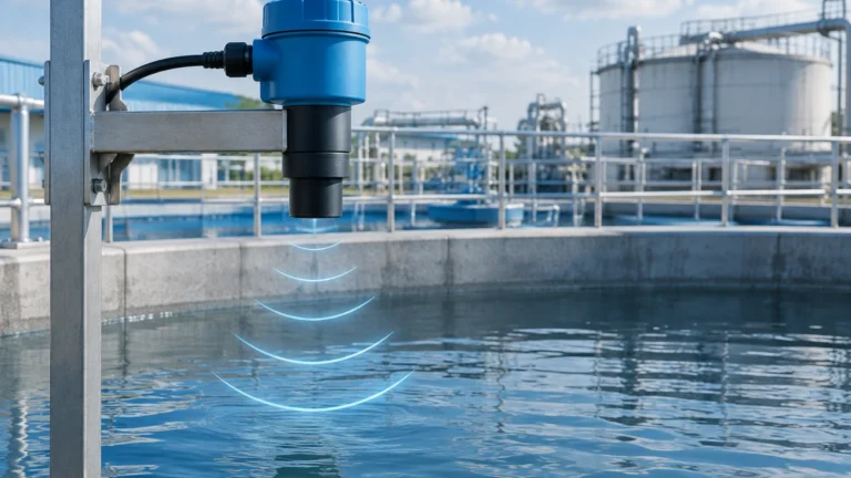
Similar to radar, ultrasonic sensors use ToF but employ sound waves instead of electromagnetic pulses. These are ideal for water treatment and simple chemical applications. The digital integration allows the system to filter out "false echoes" caused by tank obstructions (like agitators or ladders) by adjusting the signal processing parameters remotely via the proibus master controller.
Hydrostatic and Magnetic Gauges
Hydrostatic transmitters measure the pressure exerted by a liquid column, while magnetic level gauges use a float system. When equipped with digital transmitters, these mechanical or pressure-based readings are digitized, allowing for precise calibration and zero-point adjustment through the control system software.
For a comprehensive look at how these technologies can be tailored to specific industrial needs, you can visit the Main Page to review product options and application support.
Key Evaluation Criteria for Proibus Networks
When designing a level measurement system that utilizes proibus, engineers must evaluate several technical factors to ensure network stability and data integrity.
| Feature | Proibus PA (Process Automation) | Proibus DP (Decentralized Periphery) |
| :— | :— | :— |
| Application Area | Process industries, hazardous zones | Factory automation, high-speed tasks |
| Physical Layer | MBP (Manchester Coded, Bus Powered) | RS-485 |
| Data Rate | Fixed at 31.25 kbit/s | Up to 12 Mbit/s |
| Power Supply | Power delivered via the bus cable | Separate power supply usually required |
| Topology | Trunk and spur, tree, or line | Linear bus (daisy chain) |
| Max Stations | Up to 32 per segment | Up to 126 (with repeaters) |
Network Topology and Wiring
The physical layout of a proibus network significantly impacts its performance. For level measurement in large-scale tank farms, a trunk-and-spur topology is often preferred. This allows a main cable (the trunk) to run across the top of a row of tanks, with individual instruments connected via shorter cable lengths (spurs).
1. Cable Specifications: Only use certified proibus cable, which typically features a characteristic impedance of 135 to 165 ohms. Using standard shielded twisted pair cable can lead to signal reflections and communication errors.
2. Termination: Both ends of a proibus DP segment must be terminated with active terminators to prevent signal bounce. In proibus PA networks, an RC (resistor-capacitor) terminator is used.
3. Segment Lengths: For DP networks running at 1.5 Mbit/s, the maximum segment length is approximately 200 meters (656 feet). For PA networks, the limit is 1,900 meters (6,233 feet), though this is reduced if the network is installed in an intrinsically safe (Ex) area.
Installation Considerations for Level Meters
Proper installation of the level meter itself is as important as the network configuration. When installing Welk radar or ultrasonic sensors in a digital environment, consider the following:
* Addressing: Each device on the proibus network must have a unique address (0-125). This is usually set via hardware DIP switches on the instrument or through a handheld configuration tool. Address 126 is typically reserved for new devices that have not yet been commissioned.
* GSD Files: To integrate a level meter into a PLC or DCS, you must install the device-specific GSD (General Station Description) file. This file tells the controller the device’s capabilities, data formats, and available diagnostic parameters.
* Shielding and Grounding: To prevent noise from variable frequency drives (VFDs) or heavy machinery, the cable shield must be properly grounded. However, care must be taken to avoid ground loops, which can occur if there is a potential difference between the sensor location and the control room.
Limitations and Common Risks
While proibus offers significant advantages, it is not without its challenges. Understanding these limitations is key to a successful deployment.
* Complexity: Setting up a digital fieldbus requires more specialized knowledge than a simple 4-20 mA loop. Personnel must be trained in network diagnostics and software configuration.
* Distance vs. Speed: In DP networks, as the baud rate increases, the allowable cable distance decreases. High-speed communication is rarely necessary for level measurement (where levels change slowly), so lower baud rates are often chosen to maximize distance.
* Single Point of Failure: If the main trunk cable is severed, all downstream devices lose communication. Implementing redundant rings or segments can mitigate this risk, though it increases system cost.
* Environmental Interference: In environments with extreme electrical noise, fiber optic repeaters may be necessary to isolate segments of the proibus network.
Troubleshooting and Maintenance
One of the primary benefits of using proibus with Welk instruments is the wealth of diagnostic data available. Modern instruments provide status bytes that indicate if the sensor is experiencing a loss of echo, if the electronics are overheating, or if the sensor face requires cleaning.
Common Troubleshooting Steps:
1. Check Termination: Ensure that terminators are powered and correctly placed at the ends of the segment.
2. Verify Addressing: Ensure no two devices share the same address.
3. Monitor Signal Quality: Use a bus analyzer to check for signal dropouts or retries, which often indicate a damaged cable or a loose connection.
4. Cyclic vs. Acyclic Data: Ensure the PLC is correctly configured to read the cyclic data (the level value) while allowing for acyclic communication (configuration and deep diagnostics).
Frequently Asked Questions (FAQs)
Q: Can I mix different brands of level meters on the same proibus segment?
A: Yes. Proibus is an open standard. As long as each device has its correct GSD file and a unique address, you can mix Welk radar meters with other certified instruments on the same network.
Q: How many level sensors can I connect to a single proibus PA segment?
A: Theoretically, up to 32 devices. However, the actual number depends on the power consumption of each device and the total length of the cable. In hazardous areas, this number is often limited to 10 or fewer due to intrinsic safety power restrictions.
Q: What is the difference between a GSD file and a DTM?
A: A GSD file is required for the PLC to communicate with the device. A DTM (Device Type Manager) is a more complex software component used in FDT (Field Device Tool) frames to provide a graphical interface for advanced configuration and calibration of the instrument.
Q: Is proibus suitable for high-temperature applications?
A: The protocol itself is a communication standard and is not affected by temperature. However, the level meter and the cabling must be rated for the environment. Welk offers high-temperature radar sensors that can operate in process temperatures exceeding 250°C (482°F), with the digital electronics housed in a cooled or remote enclosure.
Conclusion
Implementing proibus in level measurement applications offers unparalleled data depth and system flexibility. By moving beyond simple analog signals, industrial operators can achieve higher accuracy, better diagnostic coverage, and simplified wiring architectures. Whether utilizing radar, ultrasonic, or hydrostatic sensors, the key to success lies in careful network design, adherence to installation standards, and the selection of high-quality instrumentation. For more information on selecting the right sensor for your digital network, explore the resources available on the Main Page.