Hydrostatic Level Measurement
Hydrostatic Level Measurement
Hydrostatic level measurement is one of the most established and reliable methods for determining the liquid level in industrial tanks, reservoirs, and boreholes. Based on the physical principle that the pressure at a specific point in a static liquid is proportional to the height of the liquid column above it, this technology is a cornerstone of modern process automation. For engineers and facility managers, understanding the nuances of this measurement method is essential for ensuring accuracy in water treatment, chemical processing, and oil and gas applications.
As a professional manufacturer of industrial level measurement instruments, Welk provides a range of solutions designed to meet the rigorous demands of these industries. This guide serves as a practical engineering reference for evaluating, selecting, and installing hydrostatic level measurement systems.
Measurement Principles
The fundamental principle underlying hydrostatic level measurement is Pascal’s Law. In a stationary (static) liquid, the pressure exerted by the liquid column is caused by the weight of the liquid acting under gravity.
The Hydrostatic Formula
The relationship between pressure and level is expressed by the following equation:
P = ρ × g × h
Where:
* P = Hydrostatic pressure (measured in Pascals or Bar)
* ρ (rho) = Density of the liquid (kg/m³)
* g = Acceleration due to gravity (approximately 9.81 m/s²)
* h = Height of the liquid column (meters)
In practical application, if the density of the liquid and the gravitational force remain constant, the pressure is directly proportional to the level. For example, a water column (density ≈ 1000 kg/m³) with a height of 10 meters (32.8 ft) exerts a pressure of approximately 1 bar (14.5 psi) at the base.
Open vs. Closed Systems
The measurement approach differs significantly depending on whether the vessel is open to the atmosphere or pressurized.
1. Open Tanks and Reservoirs: In an open system, the sensor measures the "gauge pressure," which is the pressure of the liquid minus the ambient atmospheric pressure. Most hydrostatic sensors use a vented cable or a reference port to automatically cancel out changes in atmospheric pressure.
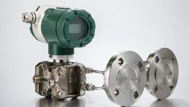
2. Closed and Pressurized Tanks: In closed vessels, the headspace above the liquid may be pressurized (e.g., nitrogen blanketing). To determine the level, the headspace pressure must be subtracted from the total pressure measured at the bottom. This typically requires a differential pressure (DP) transmitter or two synchronized pressure sensors.
Types of Hydrostatic Level Sensors
Hydrostatic measurement instruments generally fall into two categories based on their installation method: submersible and externally mounted.
1. Submersible Level Transmitters
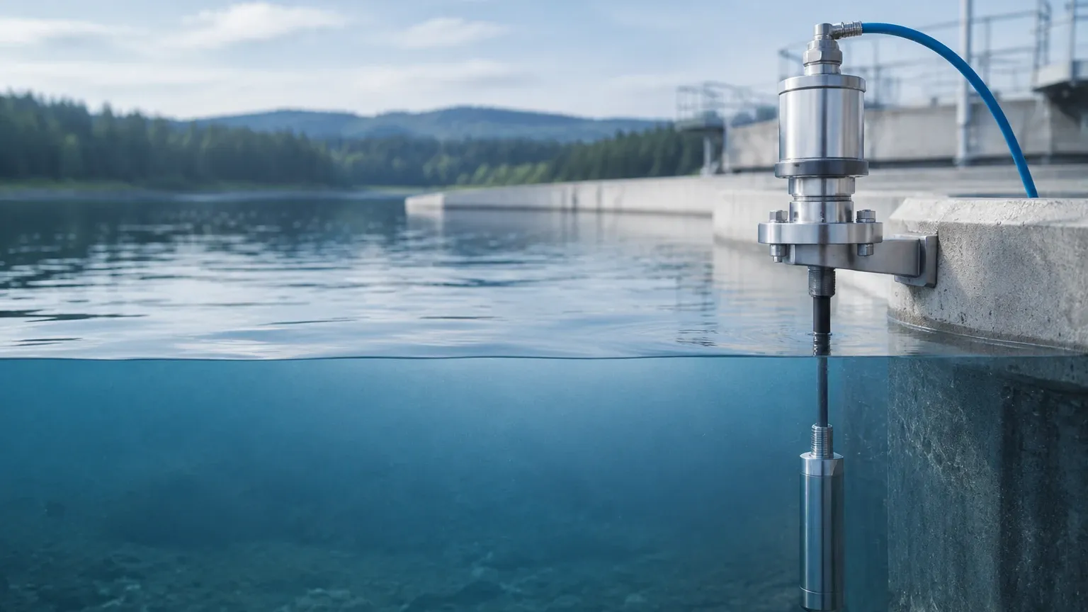
These sensors are designed to be lowered directly into the medium. They consist of a pressure-sensing diaphragm housed in a protective casing, connected to a specialized cable that provides both electrical signals and an internal vent tube for atmospheric compensation. These are ideal for deep wells, boreholes, and large open reservoirs.
2. External Pressure Transmitters
Externally mounted sensors are fixed to the outside of a tank via a flange or threaded connection at the lowest point of measurement. The diaphragm is in direct contact with the liquid through a hole in the tank wall. These are preferred for process tanks where the sensor needs to be accessible for maintenance without entering the vessel.
Key Evaluation Criteria for Selection
Selecting the correct instrument requires a thorough analysis of the process conditions. Failure to account for media characteristics can lead to significant measurement drift or sensor failure.
Media Density (Specific Gravity)
Since the sensor measures weight, any change in the liquid's density will directly affect the level reading. If a tank is used for different liquids with varying densities, the transmitter must be recalibrated or the control system must compensate for the specific gravity (SG). Temperature fluctuations also affect density; for high-precision applications, temperature compensation is mandatory.
Chemical Compatibility
The wetted parts of the sensor—including the diaphragm and the housing—must be resistant to the process media. Common materials include:
* 316L Stainless Steel: Standard for water and mild chemicals.
* Hastelloy C or Tantalum: Used for highly aggressive acids or corrosive media.
* Ceramic Diaphragms: Highly resistant to abrasion and chemical attack, often used in wastewater or slurry applications.
Pressure and Temperature Range
Ensure the sensor can withstand the maximum hydrostatic head plus any potential overpressure events. Similarly, the operating temperature must fall within the sensor’s compensated range to prevent thermal expansion errors in the diaphragm.
Selection Table: Hydrostatic Sensor Types
| Feature | Submersible Probe | External Flange Transmitter | Differential Pressure (DP) |
| :— | :— | :— | :— |
| Best Use Case | Deep wells, open pits, reservoirs | Process tanks, hygienic food/pharma | Pressurized/closed vessels |
| Installation | Suspended by cable | Flanged or threaded to tank wall | Two-port connection (top/bottom) |
| Maintenance | Easy to pull up | Requires tank drainage or isolation valve | Complex piping/manifold setup |
| Atmospheric Comp. | Via vented cable | Via reference port on housing | Inherently compensated |
| Cost | Low to Moderate | Moderate | High |
Installation Considerations
Proper installation is critical to the longevity and accuracy of hydrostatic level measurement systems. For detailed technical specifications and support, engineers should Review product options and application support on our main site.
1. Avoiding Turbulence
Sensors should not be installed directly in the path of an inflow pipe or near an agitator. The kinetic energy of moving fluid can create localized pressure fluctuations (dynamic pressure), leading to unstable readings. If turbulence is unavoidable, a stilling well (a perforated pipe) should be used to protect the sensor.
2. Cable Management and Venting
For submersible sensors, the vented cable must be protected. The vent tube allows the sensor to compensate for barometric pressure changes. If this tube becomes kinked or clogged with moisture, the measurement will drift. Use a specialized junction box with a breathable desiccant filter to prevent moisture ingress into the vent tube.
3. Mounting Position
The sensor must be located at the "zero point" of the tank. Any liquid below the sensor level is in a "dead zone" and cannot be measured. Conversely, if the sensor is mounted slightly above the bottom to avoid silt buildup, the offset must be programmed into the controller.
Limitations and Common Risks
While hydrostatic level measurement is robust, it is not a "one-size-fits-all" solution. Engineers must be aware of the following limitations:
* Density Sensitivity: As noted, this method is weight-dependent. It is not suitable for applications where the liquid density changes unpredictably (e.g., mixing processes with variable concentrations).
* Build-up and Clogging: In wastewater or viscous chemical applications, solids can accumulate on the diaphragm. A flush-mounted diaphragm or a non-clogging design is necessary to prevent false readings.
* Mechanical Damage: The sensing diaphragms are often very thin (to maintain sensitivity). They can be easily damaged by high-pressure washers or physical contact during cleaning.
Frequently Asked Questions (FAQ)
Q: How does temperature affect hydrostatic level measurement?
A: Temperature affects measurement in two ways. First, it changes the density of the liquid (as temperature rises, density usually decreases), which can cause the sensor to under-read the actual level. Second, temperature can cause the internal fill fluid of the sensor to expand. High-quality sensors include internal temperature compensation to mitigate the latter.
Q: Can I use a hydrostatic sensor for boiling liquids?
A: It is generally not recommended. Boiling creates bubbles (aeration), which significantly lowers the effective density of the liquid. Furthermore, the turbulence and vapor pressure in the headspace of a boiling vessel make hydrostatic measurement highly inaccurate.
Q: What is the difference between a gauge pressure sensor and an absolute pressure sensor in this context?
A: A gauge pressure sensor measures pressure relative to the atmosphere, which is standard for most level applications. An absolute pressure sensor measures pressure relative to a vacuum. If you use an absolute sensor for level, you must have a second absolute sensor to measure barometric pressure and subtract it manually.
Q: How long can the cable be on a submersible sensor?
A: Cables can often extend up to several hundred meters. However, signal degradation and the weight of the cable become factors. For very long runs, a 4-20mA current loop or digital output (like RS485/Modbus) is preferred to maintain signal integrity.
Conclusion
Hydrostatic level measurement remains a preferred choice for industrial applications due to its simplicity and lack of moving parts. By carefully considering liquid density, tank geometry, and chemical compatibility, engineers can implement a measurement solution that provides years of reliable service.
For professionals seeking high-performance instrumentation, Welk offers a comprehensive portfolio of level measurement technologies. To explore our full range of radar, ultrasonic, and hydrostatic instruments, visit our Main Page.