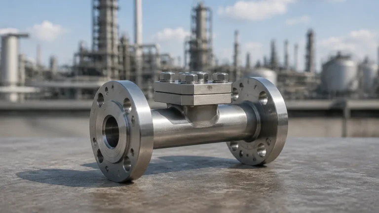
Psi Pressure Transducer
Psi Pressure Transducer
In the landscape of industrial automation and process control, the ability to quantify force exerted by fluids or gases is fundamental. A psi pressure transducer serves as the critical bridge between physical mechanical stress and electronic data. By converting pressure—specifically measured in pounds per square inch (psi)—into a measurable electrical signal, these devices enable real-time monitoring, safety interlocking, and precise inventory management in sectors ranging from municipal water treatment to complex chemical refining.
For engineers and facility managers, selecting a psi pressure transducer requires a deep understanding of both the underlying physics and the specific environmental variables of the application. As a professional manufacturer, Welk provides a range of these instruments designed to meet the rigorous demands of modern industry, ensuring that pressure data is not only accurate but also reliable over long-term deployments.
Measurement Principles of Pressure Transducers
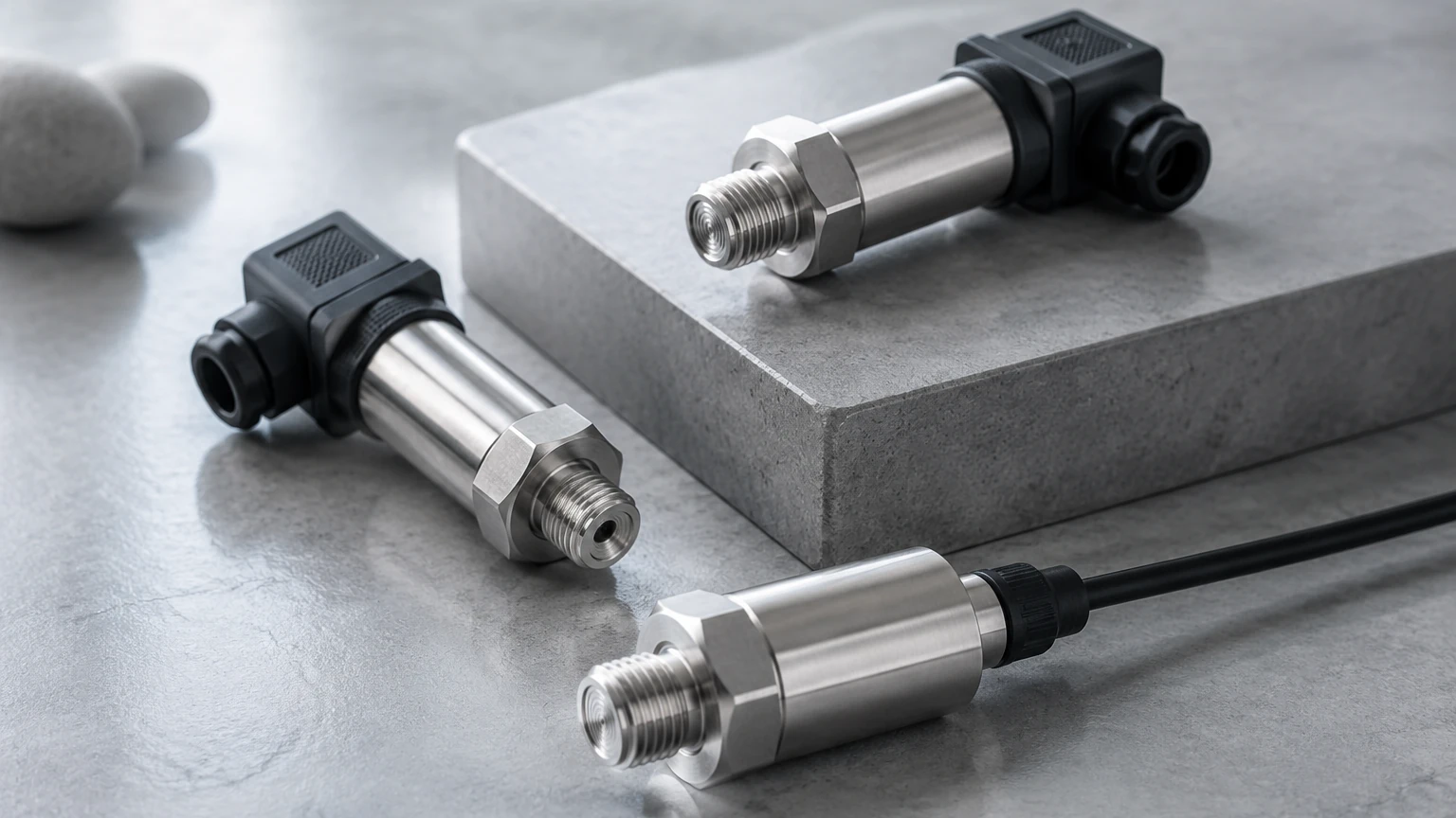
To effectively implement a psi pressure transducer, one must first understand how these devices interpret physical force. At its core, a transducer consists of two primary components: a sensing element (usually a diaphragm) and a transduction element that converts the diaphragm's displacement into an electrical signal.
Piezoresistive Sensing
This is the most common technology used in industrial transducers. It utilizes a silicon or metallic strain gauge bonded to a diaphragm. When pressure is applied, the diaphragm deforms, causing a change in the electrical resistance of the strain gauge. This change is measured using a Wheatstone bridge circuit. Piezoresistive sensors are favored for their high sensitivity and robust performance in standard temperature ranges.
Capacitive Sensing
Capacitive transducers measure the change in electrical capacitance between a flexible diaphragm and a fixed metal plate. As pressure moves the diaphragm, the distance between the plates changes, altering the capacitance. These sensors are known for their excellent stability and ability to measure very low pressure ranges (low psi) with high accuracy. They are often used in cleanroom environments or high-precision laboratory settings.
Thin-Film Technology
Thin-film transducers involve depositing a thin layer of resistive material directly onto a stainless steel diaphragm using vacuum deposition. This creates a molecular bond that is extremely resistant to shock, vibration, and thermal cycling. These are often the preferred choice for heavy industrial hydraulic systems where pressure spikes are frequent.
Translating PSI to Level: Hydrostatic Principles
While a psi pressure transducer is a pressure-measuring device, it is frequently used as a level measurement tool in liquid storage tanks. This is known as hydrostatic level measurement. The principle is based on the fact that the pressure at the bottom of a liquid column is directly proportional to the height of the liquid and its specific gravity.
In metric terms, 1 bar of pressure is equivalent to approximately 10.197 meters of water column. In imperial units, which are standard for a psi pressure transducer, 1 psi is equal to approximately 2.31 feet of water. Therefore, a transducer measuring 10 psi at the base of a water tank indicates a water level of 23.1 feet (approximately 7.04 meters).
When using these instruments for level measurement, it is vital to account for the density of the fluid. A heavier fluid, such as sulfuric acid, will exert more psi per foot of height than water, necessitating a density correction factor in the control system or the transducer’s internal calibration.
Key Evaluation Criteria for Selection
Choosing the right psi pressure transducer involves more than just matching the pressure range. Engineers must evaluate several technical specifications to ensure the device survives the process environment.
Pressure Type: Gauge, Absolute, or Sealed
* Gauge Pressure: Measures pressure relative to the local atmospheric pressure. These transducers include a vent tube in the cable to equalize the internal sensor cavity with the outside air.
* Absolute Pressure: Measures pressure relative to a perfect vacuum. These are used in applications where atmospheric pressure fluctuations would introduce unacceptable errors, such as in high-altitude aerospace applications or vacuum distillation.
* Sealed Gauge: Similar to gauge pressure but the reference chamber is sealed at a specific atmospheric pressure (usually 14.7 psi at sea level). This is used in high-pressure applications (above 500 psi) where venting is impractical.
Accuracy and Linearity
Accuracy is typically expressed as a percentage of the Full Scale (FS) output. This includes errors from non-linearity, hysteresis, and non-repeatability. For most industrial applications, an accuracy of ±0.25% to ±0.5% FS is standard, though high-precision models from Welk can offer ±0.1% FS for critical custody transfer or laboratory testing.
Output Signals
The most common output is the 4-20 mA current loop, which is highly resistant to electrical noise and can transmit data over long distances (up to 1,000 meters). Other options include 0-5V or 0-10V DC signals, which are simpler for local PLC integration but more susceptible to voltage drops and interference.
Practical Selection Table
The following table provides a general guideline for selecting a transducer based on common industrial scenarios.
| Application | Typical PSI Range | Recommended Sensor Type | Housing Material |
| :— | :— | :— | :— |
| Shallow Tank Level | 0–5 psi (0–3.5 mH2O) | Capacitive / Piezoresistive | 316L Stainless Steel |
| Deep Well Monitoring | 0–100 psi (0–70 mH2O) | Piezoresistive Submersible | 316L SS / Titanium |
| Hydraulic Systems | 0–5,000 psi (0–345 bar) | Thin-Film | 17-4 PH Stainless Steel |
| Chemical Processing | 0–50 psi (0–3.4 bar) | Ceramic Diaphragm | PVDF / Hastelloy |
| Compressed Air Lines | 0–150 psi (0–10 bar) | Standard Piezoresistive | Stainless Steel |
For a comprehensive look at available configurations and technical support for these ranges, users should consult the Main Page of our technical catalog.
Installation Considerations and Best Practices
The longevity and accuracy of a psi pressure transducer are heavily dependent on proper installation. Even the highest-quality sensor will fail if subjected to improper mounting or environmental stress.
Orientation and Mounting
In liquid applications, the transducer should ideally be mounted at the lowest point of the vessel. If the fluid contains sediment or solids, the sensor should be mounted slightly above the bottom or on the side of the tank to prevent the diaphragm from being buried in sludge. For gas applications, the transducer should be mounted above the pipeline to allow any moisture or condensate to drain away from the sensor face.
Venting and Moisture Protection
For gauge pressure transducers, the vent tube in the cable is a potential entry point for moisture. If water enters the vent tube, it can lead to internal corrosion or sensor drift. Installers must use a moisture filter or a specialized junction box that allows air to pass while blocking water vapor. Ensure the cable jacket is not kinked, as this can pinch the vent tube and cause inaccurate readings due to pressure imbalances.
Protection from Pressure Spikes
In systems with fast-acting valves or pumps, "water hammer" can create instantaneous pressure spikes that exceed the proof pressure of the transducer. To protect the sensing diaphragm, engineers should install a snubber or a capillary tube to dampen these pulses. Most Welk transducers are designed with an overpressure rating (typically 2x or 3x the rated psi), but consistent spiking will eventually fatigue the metal diaphragm.
Common Risks and Limitations
While versatile, the psi pressure transducer has limitations that must be addressed during the engineering phase.
1. Temperature Sensitivity: All pressure sensors are affected by temperature. While modern units include internal temperature compensation, extreme heat (above 85°C) can cause the signal to drift. For high-temperature steam applications, a cooling siphon or "pigtail" should be used to isolate the sensor from direct heat.
2. Media Compatibility: The diaphragm material must be chemically compatible with the process fluid. While 316L stainless steel is standard, highly corrosive fluids like hydrochloric acid require ceramic sensors or specialized coatings like PTFE or Gold plating.
3. Long-Term Drift: Over years of operation, the zero-point of a transducer may shift slightly. Regular calibration—ideally once per year—is recommended to maintain system integrity. This is particularly important in safety-instrumented systems (SIS).
Information Confirmation for Project Stakeholders
Before finalizing a purchase or beginning an installation, project engineers should confirm the following data points:
* Maximum System Pressure: Ensure the transducer's burst pressure is significantly higher than any possible system failure state.
* Electrical Environment: Determine if the installation area requires explosion-proof (Class I, Div 1) or intrinsically safe ratings.
* Cable Length and Type: For submersible psi pressure transducers, the cable must be long enough to reach the junction box without splices, and the jacket material (PUR, PVC, or FEP) must be compatible with the liquid.
* Process Connection: Confirm the thread type (NPT, G, or BSP) and size to ensure a leak-free mechanical fit.
Frequently Asked Questions
Q: What is the difference between a pressure transmitter and a pressure transducer?
A: In technical terms, a transducer typically provides a low-level voltage output (like mV), while a transmitter includes signal conditioning to provide a high-level current (4-20mA) or voltage (0-10V) output. However, in modern industrial parlance, the terms are often used interchangeably.
Q: Can I use a psi pressure transducer to measure the level of a pressurized tank?
A: Yes, but you must use a differential pressure (DP) approach. You will need to measure the pressure at the bottom of the tank and the gas pressure at the top. The difference between the two represents the hydrostatic head of the liquid.
Q: How do I know if my transducer has failed?
A: Common signs of failure include a "railing" signal (the output stays at a constant 4mA or 20mA regardless of pressure), excessive signal noise, or a significant offset where the sensor does not return to zero at atmospheric pressure. Physical inspection of the diaphragm for pitting or deformation is also recommended.
By adhering to these engineering standards and selection protocols, facilities can ensure that their pressure monitoring systems provide the precision required for optimized industrial performance. For detailed product specifications and application engineering support, visit the Main Page to explore the full range of Welk instrumentation solutions.