Pulse Flow Meter
Pulse Flow Meter
In the landscape of industrial process control, the pulse flow meter serves as a foundational component for accurate liquid and gas measurement. Unlike analog meters that provide a continuous current signal (such as 4-20mA) representing a flow rate, a pulse flow meter generates a discrete digital signal where each pulse represents a specific, calibrated volume of fluid. This "K-factor"—the number of pulses per unit of volume—allows for high-precision totalization, batching, and integration with modern Programmable Logic Controllers (PLCs) and industrial automation systems.
For engineers and procurement professionals, selecting the correct pulse flow meter requires an understanding of the underlying physics of the measurement, the chemical compatibility of the materials, and the electrical requirements of the receiving instrumentation. This guide provides a technical overview of pulse-output flow technologies, selection criteria, and installation best practices to ensure long-term reliability in demanding industrial environments.
Measurement Principles and Signal Generation
Pulse flow meters operate on various physical principles, but they all share a common goal: converting the kinetic energy or volumetric displacement of a fluid into an electrical frequency. The method of pulse generation typically falls into one of three categories: mechanical, magnetic, or electronic processing.
Mechanical and Magnetic Sensing
In many mechanical meters, such as turbine or oval gear designs, a rotating element is embedded with magnets. As the fluid forces the element to spin, the magnets pass a stationary sensor—typically a Hall Effect sensor or a Reed switch—located outside the fluid path. Each pass generates a voltage spike or a contact closure, creating a pulse train.
* Hall Effect Sensors: These require a power source and provide a high-frequency square wave output. They are preferred for high-speed applications and offer excellent longevity because they have no moving electrical parts.
* Reed Switches: These are passive, dry-contact switches that open and close in the presence of a magnetic field. While they do not require power, they are subject to mechanical wear and are generally limited to lower pulse frequencies.
Electronic Signal Processing
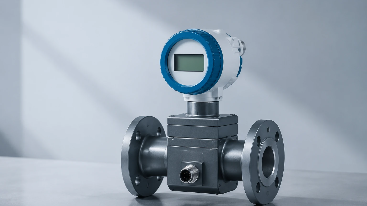
Modern non-mechanical meters, such as electromagnetic or ultrasonic flow meters, use internal digital signal processors (DSP) to calculate flow based on Faraday’s Law or transit-time differences. Once the flow rate is determined, the internal electronics convert this value into a pulse output for compatibility with legacy totalizers or batch controllers. This allows users to benefit from the maintenance-free nature of non-intrusive meters while maintaining a pulse-based architecture for dosing and filling operations.
Common Types of Pulse Flow Meters
1. Turbine Flow Meters
Turbine meters utilize a multi-bladed rotor suspended in the fluid stream. The velocity of the fluid is proportional to the rotational speed of the rotor. As the blades pass a pickup coil, they disturb the magnetic field, generating a pulse. These are highly accurate for low-viscosity liquids like water, solvents, and light fuels.
2. Positive Displacement (PD) Meters
PD meters, such as oval gear or nutating disc meters, physically entrap a fixed volume of fluid and move it from the inlet to the outlet. Because the displacement is constant, these meters are exceptionally accurate for high-viscosity fluids (oils, resins, and syrups) where turbine meters would fail due to drag. Each rotation of the internal gears corresponds to a precise volume, making them the gold standard for high-precision batching.
3. Vortex Flow Meters
Vortex meters place a "shedder bar" in the flow path. As fluid flows past this bar, vortices (swirls) are created alternately on each side. The frequency of these vortices is directly proportional to the flow velocity. A sensor detects the pressure fluctuations and converts them into a pulse signal. These are robust and ideal for steam, gas, and high-temperature liquids.
Technical Selection Criteria
When evaluating a pulse flow meter for a specific application, several technical parameters must be confirmed to ensure the device meets the project's accuracy and durability requirements.
The K-Factor
The K-factor is the most critical value provided by the manufacturer. It defines how many pulses the meter produces per liter (L) or gallon (gal). For example, a meter with a K-factor of 100 pulses/L will send 500 pulses to the PLC when 5 liters of fluid have passed. In high-precision applications, a factory calibration certificate specifying the exact K-factor is essential, as manufacturing tolerances can cause slight variations between units.
Fluid Properties
* Viscosity: High viscosity can slow down turbine rotors, leading to under-reporting. Conversely, positive displacement meters often perform better as viscosity increases because the fluid acts as a sealant between the internal gears.
* Conductivity: If using an electromagnetic meter with a pulse output, the fluid must meet a minimum conductivity threshold (typically >5 μS/cm).
* Corrosivity: Ensure that the wetted materials (316L stainless steel, PTFE, Hastelloy) are compatible with the chemical makeup of the process fluid.
Electrical Output Types
Pulse signals are typically delivered in one of three formats:
1. NPN (Sinking): The meter acts as a switch to the negative rail. Common in many Asian and European PLC configurations.
2. PNP (Sourcing): The meter provides a positive voltage pulse. Common in North American industrial systems.
3. Push-Pull: A versatile output that can both sink and source current, providing a cleaner square wave and better noise immunity over long cable runs.
Practical Selection Table
| Technology | Best Fluid Type | Accuracy | Pressure Drop | Maintenance Level |
| :— | :— | :— | :— | :— |
| Turbine | Low-viscosity liquids/Gas | ±0.25% to ±0.5% | Medium | Moderate (Moving parts) |
| Oval Gear | High-viscosity oils/Chemicals | ±0.5% | High | Moderate (Moving parts) |
| Vortex | Steam, Gas, Water | ±1.0% | Low | Low (No moving parts) |
| Electromagnetic | Conductive liquids/Slurries | ±0.2% to ±0.5% | Negligible | Very Low |
| Ultrasonic | Clean liquids | ±1.0% | None | Very Low |
Installation Considerations
Proper installation is paramount to achieving the rated accuracy of a pulse flow meter. Mechanical meters are particularly sensitive to the flow profile of the incoming fluid.
Straight Pipe Requirements
To eliminate turbulence caused by elbows, valves, or pumps, most pulse flow meters require a specific length of straight pipe before and after the unit. A standard rule of thumb is "10D Upstream and 5D Downstream," meaning if the pipe diameter (D) is 50 mm (2 inches), there should be 500 mm (20 inches) of straight pipe before the meter and 250 mm (10 inches) after it.
Orientation and Trapped Air
* Horizontal vs. Vertical: Most meters can be installed in either orientation, but for vertical installations, the flow should always be upward. This ensures the pipe remains full and prevents air pockets from forming.
* Air Elimination: Pulse flow meters cannot distinguish between air and liquid. If air bubbles pass through a turbine meter, the rotor will spin at extremely high speeds, leading to massive measurement errors and potential mechanical damage. In systems prone to aeration, an air eliminator should be installed upstream.
Electrical Noise and Shielding
Pulse signals, especially those from high-impedance sensors, are susceptible to Electromagnetic Interference (EMI) from Variable Frequency Drives (VFDs) and large motors. Always use shielded, twisted-pair cabling and ensure the shield is grounded at only one end (typically the PLC side) to prevent ground loops.
Common Risks and Limitations
Despite their versatility, pulse flow meters have specific limitations that must be managed:
1. Pressure Drop: Mechanical meters like turbine and PD types extract energy from the fluid to move the internal components. This results in a pressure drop across the meter. Engineers must verify that the system has sufficient head pressure to overcome this loss at maximum flow rates.
2. Solids and Debris: Suspended solids can clog oval gears or damage turbine blades. A strainer (typically 40 to 80 mesh) should be installed upstream of any mechanical pulse flow meter.
3. Signal Aliasing: If the pulse frequency is too high for the PLC's digital input card to sample, pulses will be missed. High-speed counter (HSC) modules are often required for meters with high K-factors or high flow rates.
Maintenance and Troubleshooting
In B2B industrial environments, downtime is costly. A robust maintenance schedule for pulse flow meters should include:
* Zero-Flow Check: Ensure the meter is not producing pulses when the pumps are off, which could indicate electrical noise or a leaking valve.
* Mechanical Inspection: For turbine and PD meters, check for bearing wear or gear pitting every 12 to 24 months, depending on the lubricity of the fluid.
* K-Factor Verification: Over time, erosion of turbine blades or gear edges can change the meter's geometry, shifting the K-factor. Periodic master-meter testing or gravimetric calibration is recommended to maintain system integrity.
For organizations looking to integrate these sensors into a broader automation framework, it is helpful to consult a professional manufacturer to match the sensor type with the specific environmental conditions. You can Review product options and application support at our Main Page to find the right balance of accuracy and cost-effectiveness for your project.
Frequently Asked Questions (FAQ)
Q: Can a pulse flow meter measure bidirectional flow?
A: Standard pulse outputs usually only provide a frequency regardless of direction. However, some dual-channel pulse meters (Quadrature output) can indicate direction by comparing the phase shift between two separate pulse trains.
Q: What is the maximum distance I can run a pulse signal?
A: For NPN or PNP signals, the limit is typically 100 to 300 meters (approx. 330 to 1000 feet) depending on cable quality and interference. For longer distances, a 4-20mA signal or a digital protocol like Modbus RS485 is preferred.
Q: How do I calculate the flow rate from the pulses?
A: The flow rate is calculated using the formula:
*Flow Rate = (Frequency in Hz / K-factor) × Time Conversion Factor.*
If your meter has a K-factor of 10 pulses/L and you measure 50 Hz (50 pulses per second), the flow rate is 5 Liters per second (300 L/min).
By adhering to these engineering principles and selection guidelines, industrial operators can ensure that their pulse flow meter installations provide the accurate, repeatable data necessary for efficient process management and quality control.