Re Electrification
Re Electrification
In the current industrial landscape, re electrification represents a fundamental shift in how processing plants, water treatment facilities, and chemical refineries manage their operations. This process involves transitioning from legacy mechanical, pneumatic, or fossil-fuel-reliant systems to modern, high-precision electrical and electronic infrastructures. A critical component of this transition is the integration of advanced level measurement instrumentation, which provides the data necessary for automated control and energy efficiency. For professionals seeking to modernize their facilities, reviewing the latest Main Page product options is a vital first step in identifying the right technology for their specific application.
Understanding Re Electrification in Process Industries
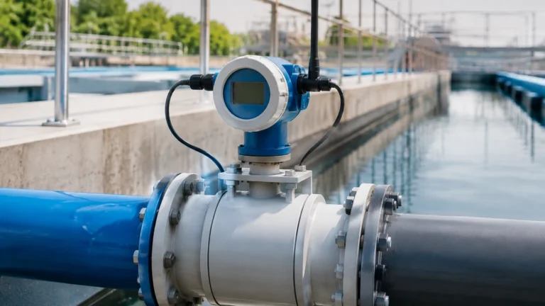
Re electrification is more than just a change in power source; it is a comprehensive upgrade of the control and monitoring layer of an industrial site. In the context of level measurement, this often means replacing manual dip-sticking or mechanical float switches with electronic sensors like radar, ultrasonic, or hydrostatic transmitters.
This shift is driven by the need for higher accuracy, real-time data acquisition, and the integration of assets into a centralized Distributed Control System (DCS) or Programmable Logic Controller (PLC). By electrifying the measurement layer, facilities can achieve better resource management, reduce waste, and improve safety by removing personnel from hazardous measurement locations.
Core Principles of Level Measurement Technologies
Before implementing a re electrification strategy, it is essential to understand the physical principles governing modern level sensors. Each technology interacts differently with the medium and the environment.
Radar Level Measurement (Time-of-Flight)
Radar level meters, particularly those operating at high frequencies like 80GHz, utilize the Time-of-Flight (ToF) principle. The sensor emits a high-frequency electromagnetic pulse that travels to the surface of the medium, reflects, and returns to the sensor. The distance is calculated based on the time interval and the speed of light. Because radar waves do not require a medium for propagation, they are unaffected by vacuum, pressure, or temperature fluctuations.
Ultrasonic Level Sensors
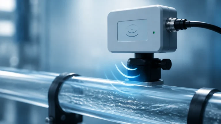
Ultrasonic sensors function similarly to radar but use sound waves instead of electromagnetic pulses. The transducer emits an ultrasonic pulse that reflects off the surface of the liquid or solid. The time taken for the echo to return is proportional to the distance. While cost-effective, ultrasonic measurement is sensitive to air temperature, heavy foam, and dust, which can attenuate the sound signal.
Hydrostatic Level Transmitters
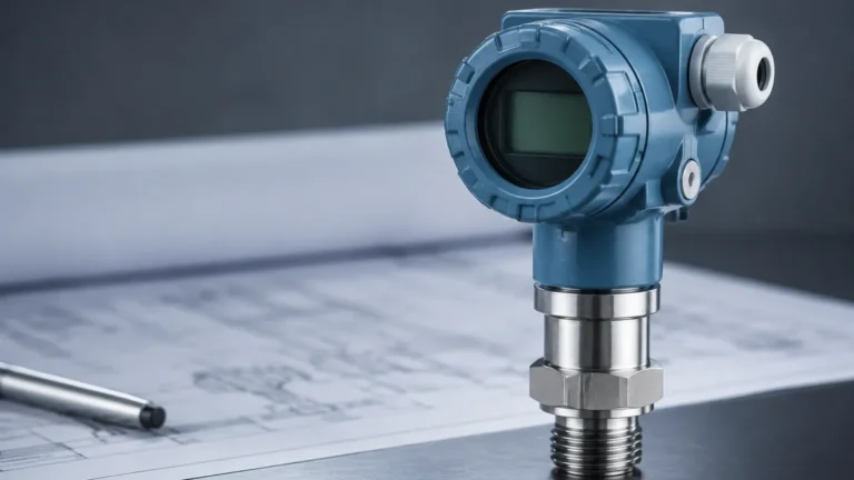
Hydrostatic measurement is based on the principle that the pressure at a specific depth in a liquid is proportional to the height of the liquid column above it. The formula used is $P = \rho \cdot g \cdot h$, where $P$ is pressure, $\rho$ is the density of the liquid, $g$ is gravity, and $h$ is the height. These sensors are typically submerged or mounted at the bottom of a tank, converting the measured pressure into an electrical signal (usually 4-20mA).
The Role of Level Sensors in Re Electrification Projects
When a facility undergoes re electrification, the goal is often to optimize power consumption and automate processes. Level sensors act as the "eyes" of the system, providing the feedback loops required for:
1. Pump Control Optimization: Automated level monitoring allows for Variable Frequency Drives (VFDs) to adjust pump speeds based on actual demand, significantly reducing electrical peak loads.
2. Inventory Management: Digital level data enables real-time tracking of raw materials and finished products, facilitating better supply chain integration.
3. Safety and Overfill Prevention: Electronic level switches and continuous transmitters provide redundant safety layers that can trigger emergency shutdowns (ESD) more reliably than mechanical alternatives.
4. Data Integration: Modern electronic sensors support protocols such as HART, Modbus RS485, and Profibus, which are essential for the digital backbone of a re-electrified plant.
Practical Selection Criteria for Upgrading Systems
Selecting the appropriate instrument during a re electrification project requires a thorough evaluation of the application's physical and chemical properties. The following table provides a comparison of the primary technologies used in modern industrial settings.
Technology Comparison Table
| Feature | Radar (80GHz) | Ultrasonic | Hydrostatic | Magnetic Gauge |
| :— | :— | :— | :— | :— |
| Measurement Type | Non-contact | Non-contact | Contact (Pressure) | Contact (Visual/Switch) |
| Accuracy | ±1mm to ±2mm | ±0.25% to ±0.5% | ±0.1% to ±0.5% | Dependent on scale |
| Max Range | Up to 120m | Up to 30m | Up to 200m (H2O) | Up to 6m (standard) |
| Process Temp. | -40°C to +250°C | -40°C to +80°C | -20°C to +80°C | -40°C to +400°C |
| Pressure Limit | High (up to 4MPa+) | Atmospheric | High (Submerged) | High (up to 16MPa+) |
| Best For | Corrosives, solids, high precision | Water treatment, open channels | Deep wells, vented tanks | High-temp boilers, visual check |

Installation Considerations for Re-Electrified Infrastructure
Transitioning to a fully electrified measurement system requires careful planning regarding the physical installation and the electrical environment.
Power Supply and Wiring
Most modern level transmitters are 2-wire or 4-wire devices. In a re electrification context, ensuring a stable 24V DC power supply is critical. Legacy plants may have significant electrical noise; therefore, shielded twisted-pair cables should be used to prevent signal interference. Proper grounding of the instrument housing is mandatory to protect sensitive electronics from surges.
Signal Integration
When replacing mechanical gauges, engineers must decide how the signal will be processed. While the 4-20mA analog signal remains the industry standard due to its robustness over long distances, re electrification often involves moving toward digital communication. RS485 Modbus allows for multiple sensors to be daisy-chained, reducing wiring costs and providing more diagnostic data to the control room.
Mounting and Positioning
For non-contact sensors (Radar and Ultrasonic), the "blocking distance" or "dead zone" must be considered. This is the area immediately below the sensor where measurement is not possible. Additionally, sensors should be mounted away from the tank wall and internal obstructions like ladders or agitators to avoid false echoes.
Limitations and Risk Mitigation
While re electrification offers numerous benefits, engineers must be aware of the limitations inherent in electronic level measurement:
* Dielectric Constant ($ε_r$): Radar sensors rely on the reflectivity of the medium. Materials with very low dielectric constants (like certain oils or liquefied gases) may require a guided wave radar (GWR) or a stilling well to concentrate the signal.
* Environmental Interference: Ultrasonic sensors can fail in the presence of heavy steam or surface foam. In these instances, switching to a high-frequency radar is often the recommended solution.
* Power Stability: Electronic instruments are sensitive to voltage fluctuations. In regions with unstable power grids, the use of Uninterruptible Power Supplies (UPS) or surge protectors is essential for maintaining continuous monitoring.
Frequently Asked Questions (FAQ)
Q: Can I use radar level meters for solids in a re electrification project?
A: Yes. 80GHz radar is particularly effective for solids because its narrow beam angle (often as small as 3 degrees) avoids interference from tank walls and can accurately measure the uneven surfaces of grain, cement, or plastic pellets.
Q: What is the benefit of RS485 over 4-20mA?
A: RS485 (Modbus) allows for digital, bi-directional communication. It can transmit not only the level value but also the temperature, signal strength, and device diagnostics over a single pair of wires, which simplifies the re electrification of large tank farms.
Q: How does re electrification impact maintenance schedules?
A: Generally, maintenance is reduced. Mechanical systems have moving parts that wear out, whereas non-contact electronic sensors have no moving parts. However, periodic calibration checks and ensuring the sensor face remains clean are still required.
Q: Is it possible to electrify level measurement in hazardous areas?
A: Absolutely. Most modern level transmitters are available with Intrinsically Safe (Ex ia) or Explosion-Proof (Ex d) ratings, making them suitable for use in oil and gas or chemical applications where flammable vapors are present.
Conclusion
The journey toward re electrification is a strategic investment in the longevity and efficiency of industrial operations. By replacing outdated measurement methods with precise, electronic level transmitters, companies can unlock new levels of automation and data-driven decision-making. Whether the application involves wastewater management, chemical processing, or bulk solids storage, selecting the right technology—be it radar, ultrasonic, or hydrostatic—is the cornerstone of a successful modernization project. For detailed technical specifications and support in choosing the right instruments for your facility, ensure you consult professional resources and review the Main Page for the latest innovations in level measurement technology.