Thermowell Pipe
Thermowell Pipe
In industrial process control, the integrity of measurement instrumentation is paramount to both safety and efficiency. Among the most critical components in thermal management and fluid monitoring systems is the thermowell pipe. A thermowell is a cylindrical pressure-tight fitting used to protect temperature sensors—such as thermocouples, thermistors, and resistance temperature detectors (RTDs)—from the corrosive effects, high pressures, and high velocities of process fluids. By acting as a barrier, the thermowell pipe allows for the removal and replacement of a sensor without requiring the shutdown of the process or the drainage of the vessel.
While often discussed in the context of temperature, thermowell pipes are integral to the broader ecosystem of industrial automation and vessel management. In many applications, temperature data is used alongside level measurement to calculate mass or volume accurately, particularly in chemical and oil and gas industries. Understanding the engineering principles behind these components is essential for any professional involved in process design.
Measurement Principles and Functionality
The primary function of a thermowell pipe is to facilitate heat transfer from the process medium to the sensing element while maintaining a pressure-tight seal. The measurement principle relies on thermal conduction through the walls of the thermowell.
When a thermowell is inserted into a pipe or tank, the process fluid flows around it. Heat is transferred from the fluid to the outer surface of the thermowell, through the material of the well, and into the internal cavity where the sensor is housed. To ensure accuracy, the sensor must be in physical contact with the bottom of the thermowell bore, often aided by a spring-loaded mechanism.
Thermal Lag and Accuracy
Because the thermowell adds a layer of material between the process fluid and the sensor, it introduces a "thermal lag." This is the delay in the sensor’s response to changes in the process temperature. The magnitude of this lag depends on the material's thermal conductivity, the wall thickness of the thermowell, and the velocity of the fluid. Engineering a thermowell pipe requires a balance between structural robustness (thicker walls for high pressure) and measurement responsiveness (thinner walls for faster heat transfer).
Types of Thermowell Pipe Designs
Thermowells are classified based on their connection type and the shape of their shank (the portion inserted into the process). Selecting the correct design is vital for ensuring the longevity of the instrument and the safety of the piping system.
1. Connection Types
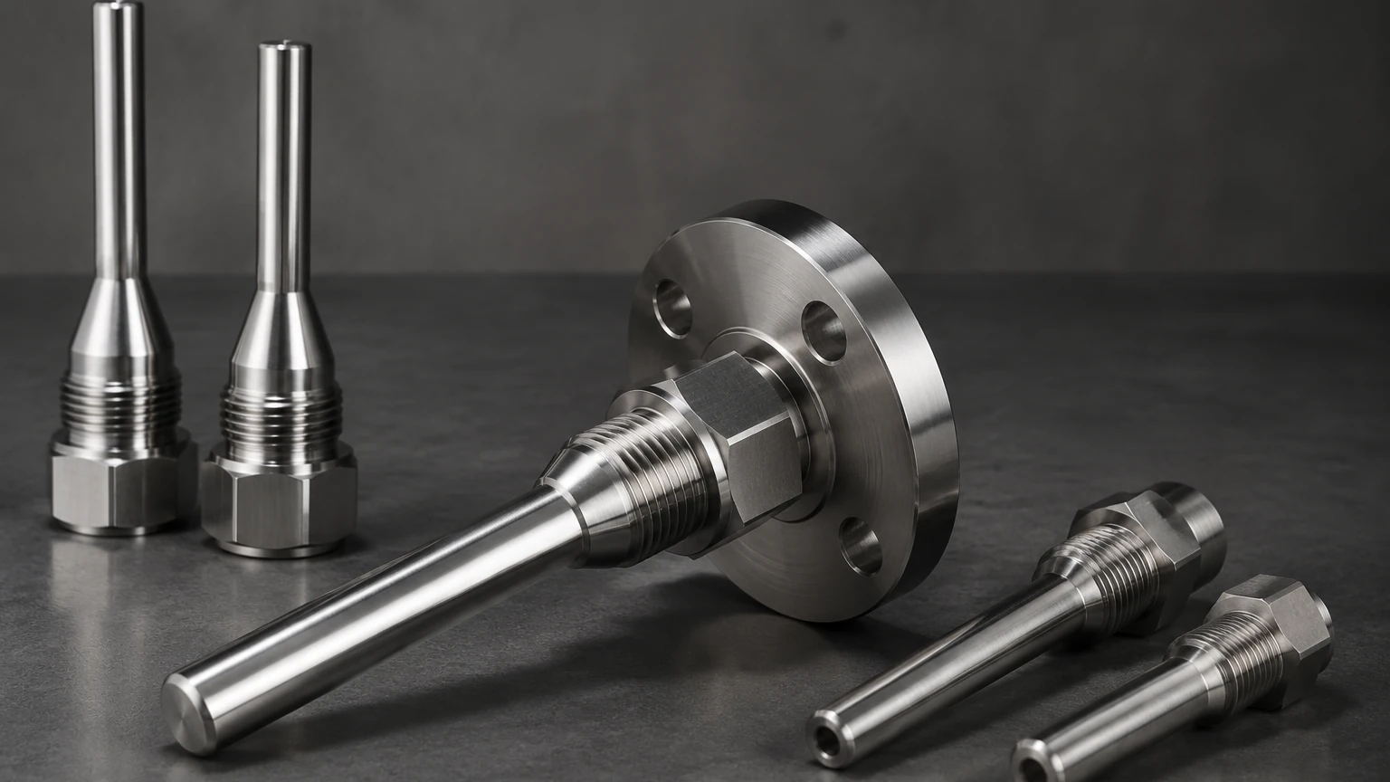
* Threaded Thermowells: These are screwed into a threaded pipe fitting or a NPT (National Pipe Thread) half-coupling. They are common in smaller pipes and lower-pressure applications where welding is not preferred.
* Flanged Thermowells: These feature a flange collar that bolts onto a mating flange on the process vessel or pipe. They are the standard for high-pressure, high-temperature, and highly corrosive environments due to their ease of removal and superior sealing.
* Socket Weld Thermowells: These are welded directly into a pipe socket. They provide a permanent, leak-proof connection suitable for high-velocity and high-pressure steam lines where maintenance frequency is low.
* Weld-In Thermowells: These are welded directly into a hole in the process pipe. They are used when a flange connection is not feasible and a permanent installation is required.
2. Shank Geometries
* Straight Shank: The diameter is uniform throughout the entire insertion length. These are easy to manufacture and provide good protection in low-velocity applications.
* Stepped Shank: The diameter is reduced at the tip (usually from 19 mm to 12.5 mm). This design reduces the mass at the sensing point, significantly improving response time while maintaining strength at the base.
* Tapered Shank: The diameter gradually decreases from the base to the tip. This design offers the best strength-to-weight ratio and is highly resistant to vibration caused by high-velocity fluid flow.
Practical Selection Table
Choosing the right thermowell pipe involves evaluating the process conditions against the mechanical properties of the well. The following table provides a general comparison of common configurations:
| Feature | Threaded Thermowell | Flanged Thermowell | Socket Weld Thermowell |
| :— | :— | :— | :— |
| Pressure Rating | Low to Medium | High to Very High | High |
| Installation Ease | High (Screw-in) | Moderate (Bolting) | Low (Requires Welding) |
| Maintenance | Easy to replace | Easiest for inspection | Difficult (Must be cut out) |
| Common Sizes | 1/2", 3/4", 1" NPT | 1" to 3" Flanges | 3/4" or 1" Pipe sizes |
| Typical Material | 316 Stainless Steel | 316SS, Monel, Hastelloy | Carbon Steel, Chrome-Moly |
| Best Application | Water lines, HVAC | Chemical reactors, Oil & Gas | High-pressure steam |
Engineering Considerations: Wake Frequency and Stress
One of the most critical risks associated with a thermowell pipe is mechanical failure due to fluid-induced vibration. As fluid flows past a cylindrical object like a thermowell, it creates vortices (swirls) in its wake. This is known as the Von Karman effect. If the frequency of these vortices matches the natural frequency of the thermowell, resonance occurs, leading to rapid fatigue and catastrophic failure.
Engineers must perform a Wake Frequency Calculation according to the ASME PTC 19.3 TW standard. This standard evaluates four specific criteria:
1. Frequency Ratio: The ratio of the wake frequency to the thermowell’s natural frequency must be within safe limits (typically < 0.8).
2. Static Stress: The steady-state stress caused by fluid pressure and drag must not exceed the material's allowable stress.
3. Dynamic Stress: The cyclic stress caused by vortex shedding must not exceed the fatigue limit.
4. Hydrostatic Pressure: The external pressure must not exceed the collapse pressure of the thermowell pipe.
Installation Guidelines
Proper installation of a thermowell pipe is as important as its design. Incorrect placement can lead to inaccurate readings or premature failure.
Insertion Length (U-Length)
The insertion length is the distance from the tip of the thermowell to the underside of the thread or flange. For liquid applications, the rule of thumb is an insertion length equal to 10 times the tip diameter. For gas applications, the length should be 15 to 20 times the diameter to account for the lower heat transfer coefficient of gases. In pipes, the tip should ideally reach the center one-third of the pipe diameter to ensure it is measuring the bulk temperature rather than the temperature near the pipe wall.
Orientation
* Perpendicular: The most common installation, where the thermowell is installed at a 90-degree angle to the flow.
* Elbow Installation: In smaller pipes, the thermowell is often installed in an elbow, pointing upstream. This allows for a longer insertion length without obstructing the flow path excessively.
* Angled Installation: In some cases, the well is installed at a 45-degree angle pointing upstream to increase the surface area exposed to the flow while reducing the drag force compared to a perpendicular installation.
Lagging Extension (T-Length)
If the pipe or vessel is insulated, a lagging extension is required. This is an extra length of the thermowell that extends beyond the connection to clear the insulation, allowing the head of the sensor to be accessible.
Limitations and Common Risks
While thermowell pipes are robust, they are not without limitations:
* Corrosion: Even stainless steel can succumb to pitting or stress corrosion cracking in the presence of chlorides or acids. Material selection must be matched to the chemical composition of the process fluid.
* Erosion: In slurries or high-velocity steam, the outer surface of the thermowell can be eroded over time. Hardened coatings or specialized materials like Stellite may be required.
* Response Time: In processes requiring rapid control (e.g., fast-acting exothermic reactions), the lag introduced by a thermowell may be unacceptable. In such cases, specialized thin-wall designs or direct-immersion sensors (with appropriate safety protocols) might be considered.
* Bore Contamination: If moisture or contaminants enter the internal bore of the thermowell, it can cause the sensor to corrode or create a thermal bridge that skews the reading.
Integration with Level Measurement Systems
In many industrial settings, temperature and level measurement go hand-in-hand. For instance, in a large fuel storage tank, the volume of the liquid changes with temperature. To calculate the standardized volume (e.g., at 15°C), the system must have accurate temperature data from thermowell-protected sensors at various depths.
Welk provides a comprehensive range of industrial level measurement instruments that often work in tandem with temperature monitoring systems. For engineers looking to integrate these technologies, it is helpful to Review product options and application support on our Main Page to ensure that all instrumentation—whether for level, pressure, or temperature—is compatible with the specific process environment.
Frequently Asked Questions (FAQ)
Q: What is the standard material for a thermowell pipe?
A: 316 Stainless Steel is the industry standard due to its excellent balance of corrosion resistance, strength, and cost. However, for extreme environments, materials like Monel 400, Inconel 600, or Hastelloy C-276 are used.
Q: Can I use a thermowell in a pipe smaller than 4 inches?
A: Yes, but it usually requires an elbow installation or a pipe tee to ensure the thermowell does not restrict flow too much and has sufficient insertion depth for an accurate reading.
Q: How often should thermowells be inspected?
A: Inspection frequency depends on the severity of the process. In non-corrosive service, they may last for decades. In high-velocity or corrosive service, annual ultrasonic thickness testing or visual inspection during shutdowns is recommended.
Q: Does a thermowell need to be grounded?
A: While the thermowell itself is typically grounded through its connection to the metal piping or vessel, the sensor inside may need specific grounding or shielding to prevent electrical noise from affecting the signal, especially with thermocouples.
Conclusion
The thermowell pipe is a deceptively simple component that performs a vital role in industrial process safety and data accuracy. By understanding the principles of heat transfer, the mechanical stresses of fluid flow, and the importance of material selection, engineers can specify solutions that protect sensitive instrumentation while maintaining process integrity. Whether you are managing a water treatment facility or a complex chemical refinery, the correct application of thermowell technology is a cornerstone of reliable automation. For more information on how these components integrate with level sensors and other process instruments, visit our Main Page.