Rtd Sensing Element
Rtd Sensing Element
In the realm of industrial process control, precision temperature measurement is as critical as pressure or flow monitoring. At the heart of this precision lies the RTD sensing element. Resistance Temperature Detectors (RTDs) are sensors used to measure temperature by correlating the electrical resistance of the RTD element with temperature. As a fundamental component in modern automation, understanding the nuances of the RTD sensing element is essential for engineers designing systems for water treatment, chemical processing, and oil and gas applications.
This guide provides a comprehensive technical overview of RTD sensing elements, their operational principles, selection criteria, and their vital role in supporting accurate level measurement technologies. For those seeking specific hardware configurations or technical consultation, you may visit the Main Page of our product catalog.
Measurement Principles of the RTD Sensing Element
The operation of an RTD sensing element is based on the physical property of metals to change their electrical resistance in response to temperature changes. This phenomenon is known as the temperature coefficient of resistance (TCR). In most metals, the electrical resistance increases as the temperature rises, a characteristic referred to as a positive temperature coefficient (PTC).
The Resistance-Temperature Relationship
For industrial applications, Platinum (Pt) is the most common material used in an RTD sensing element due to its chemical inertness, wide temperature range, and highly linear resistance-to-temperature relationship. The standard relationship is defined by the Callendar-Van Dusen equation. For temperatures above 0°C, the formula is simplified to:
Rt = R0 (1 + At + Bt²)
Where:
* Rt is the resistance at temperature t.
* R0 is the resistance at 0°C (typically 100Ω for Pt100).
* A and B are constants derived from the properties of the platinum used.
Sensitivity and Alpha Values
The sensitivity of an RTD sensing element is often denoted by its "Alpha" (α) value, which represents the average change in resistance per unit of temperature between 0°C and 100°C. The industry standard Alpha for platinum RTDs is 0.00385 Ω/Ω/°C (DIN/IEC 60751). This means a Pt100 sensor with a resistance of 100.00Ω at 0°C will have a resistance of 138.51Ω at 100°C.
Types of RTD Sensing Elements
There are two primary constructions for an RTD sensing element: thin-film and wire-wound. Each offers distinct advantages depending on the environmental stressors and accuracy requirements of the application.
Thin-Film RTD Elements
Thin-film elements are manufactured by depositing a very thin layer of platinum onto a ceramic substrate using vacuum sputtering. The platinum layer is then etched into a resistive circuit and laser-trimmed to achieve the desired R0 value. Finally, the element is coated with glass or epoxy for protection.
* Advantages: High vibration resistance, small footprint (compact size), and lower cost due to the minimal amount of platinum used.
* Limitations: Generally limited to lower temperature ranges (typically up to 500°C) and slightly higher drift compared to wire-wound versions.
Wire-Wound RTD Elements
Wire-wound elements consist of a fine platinum wire coiled around a ceramic or glass mandrel (core). In "partially supported" designs, the wire is threaded through small holes in a ceramic insulator. This construction allows the wire to expand and contract freely with temperature changes, minimizing mechanical strain.
* Advantages: Highest accuracy, excellent stability over long periods, and capable of measuring temperatures up to 850°C.
* Limitations: More expensive to manufacture and more susceptible to damage from high-frequency vibrations.
Selection Criteria for Industrial Applications
Choosing the correct RTD sensing element requires balancing accuracy, temperature range, and environmental durability. The following table summarizes the key evaluation criteria for standard industrial elements.
RTD Element Comparison Table
| Feature | Thin-Film Element | Wire-Wound (Ceramic) | Wire-Wound (Glass) |
| :— | :— | :— | :— |
| Temperature Range | -50°C to +500°C | -200°C to +850°C | -200°C to +400°C |
| Accuracy (IEC 60751) | Class A, B | Class AA, A, B | Class A, B |
| Vibration Resistance | Excellent | Fair | Good |
| Long-term Stability | Good | Excellent | Very Good |
| Response Time | Fast | Moderate | Moderate |
| Typical Applications | HVAC, General Industry | Power Plants, Labs | Chemical Processing |
Accuracy Classes
When specifying an RTD sensing element, engineers must select an accuracy class defined by IEC 60751. The tolerance (Δt) is calculated as follows:
* Class AA (1/10 DIN): ±(0.1 + 0.0017|t|) °C
* Class A: ±(0.15 + 0.002|t|) °C
* Class B: ±(0.3 + 0.005|t|) °C
For most industrial process automation, Class A provides the necessary precision for critical control loops, while Class B is often sufficient for general monitoring.
Integration with Level Measurement Systems
While the RTD sensing element is a temperature sensor, its role in level measurement is indispensable. Many level measurement technologies rely on the physical properties of the medium, which are often temperature-dependent.
Hydrostatic Level Transmitters
In hydrostatic level measurement, the sensor measures the pressure exerted by a liquid column. However, the density of a liquid changes with temperature. An integrated RTD sensing element allows the transmitter to perform real-time density compensation, ensuring that the calculated level (in meters or millimeters) remains accurate even if the process fluid heats up or cools down.
Radar and Ultrasonic Level Sensors
In ultrasonic level measurement, the speed of sound through air or gas is highly dependent on temperature. A 1°C change in temperature can result in a 0.17% error in distance measurement. High-quality ultrasonic systems incorporate an RTD to provide the necessary data for the algorithm to adjust the time-of-flight calculation. Similarly, in guided wave radar (GWR) applications involving high-pressure steam, temperature data is used to correct for the dielectric constant changes in the vapor space.
To see how these sensors are integrated into complete measurement packages, you can Review product options and application support on our main site.
Installation and Maintenance Considerations
The performance of an RTD sensing element is heavily influenced by how it is installed and wired into the control system. Improper installation can lead to significant measurement errors, even with a high-accuracy element.
Wiring Configurations
Since an RTD is a resistance-based device, the resistance of the lead wires connecting the element to the transmitter can introduce errors. There are three common wiring methods:
1. 2-Wire: The simplest but least accurate. The lead wire resistance is added directly to the element's resistance, causing a positive temperature offset. It is only suitable for very short distances.
2. 3-Wire: The industrial standard. A third wire allows the transmitter to measure and subtract the lead wire resistance, assuming all leads have the same resistance. This provides a balance between cost and accuracy.
3. 4-Wire: The most accurate method. It uses two leads to carry the excitation current and two leads to measure the voltage drop across the element. This completely eliminates the impact of lead wire resistance and is used for Class AA sensors and laboratory calibrations.
Thermowell Usage
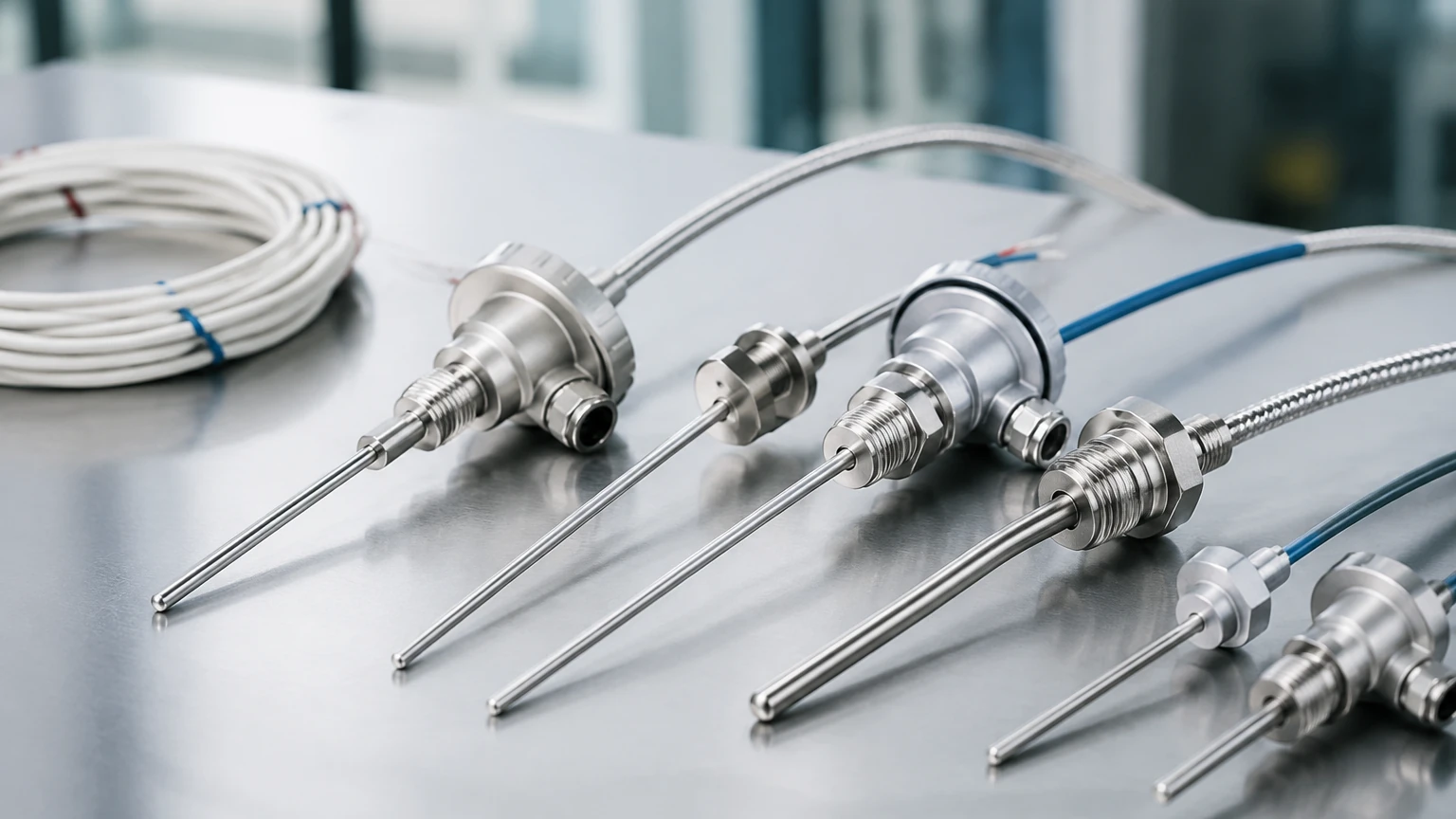
In industrial tanks and pipes, the RTD sensing element is rarely exposed directly to the process fluid. Instead, it is housed within a thermowell. The thermowell protects the sensor from high pressures, corrosive chemicals, and high-velocity flows. When installing, it is vital to ensure the sensor tip is in firm contact with the bottom of the thermowell to minimize thermal lag. The use of thermal transfer paste can further improve response times.
Immersion Depth
To avoid "stem conduction" errors—where heat is conducted away from the sensing element by the sensor sheath—the element must be immersed to a sufficient depth. A general rule of thumb is an immersion depth equal to 10 times the diameter of the sensor sheath plus the length of the sensing element itself.
Limitations and Common Risks
While the RTD sensing element is highly reliable, certain factors can compromise its integrity:
* Self-Heating: To measure resistance, a small current must be passed through the element. This current generates a small amount of heat (I²R). If the excitation current is too high (typically >1mA), it can raise the temperature of the element above the actual process temperature.
* Mechanical Stress: Excessive vibration or physical shock can fracture the ceramic substrate of a thin-film element or cause the fine wires in a wire-wound element to break or short-circuit.
* Moisture Ingress: If the seal of the sensor probe is compromised, moisture can enter the assembly. This creates a parallel resistance path (shunting), which typically results in a lower-than-actual temperature reading and erratic behavior.
* Contamination: At very high temperatures, metal ions from the sheath can migrate into the platinum lattice of the RTD sensing element, permanently altering its resistance-temperature curve (poisoning).
Frequently Asked Questions (FAQs)
Q: What is the difference between Pt100 and Pt1000?
A: A Pt100 element has a resistance of 100Ω at 0°C, while a Pt1000 has 1000Ω at 0°C. Pt1000 elements are often used in battery-powered or low-power applications because the higher resistance allows for lower excitation currents, reducing self-heating and power consumption.
Q: How often should an RTD sensing element be calibrated?
A: For most industrial processes, an annual calibration check is recommended. However, in high-vibration or high-temperature environments, more frequent checks may be necessary to monitor for sensor drift.
Q: Can I use an RTD in a hazardous area?
A: Yes, RTDs are inherently simple devices. When used with appropriate intrinsic safety (IS) barriers or housed in explosion-proof enclosures, they are suitable for use in Zone 0, 1, and 2 environments.
Q: Why choose an RTD over a Thermocouple?
A: RTDs offer higher accuracy, better repeatability, and superior long-term stability compared to thermocouples. Thermocouples are generally preferred only for extremely high temperatures (above 850°C) or applications requiring an ultra-fast response time.
Conclusion
The RTD sensing element remains the gold standard for industrial temperature measurement due to its reliability and precision. Whether it is used for monitoring chemical reactions or providing thermal compensation for hydrostatic level transmitters, selecting the right element construction and wiring configuration is paramount for process safety and efficiency. By adhering to proper installation guidelines and understanding the limitations of the technology, engineers can ensure long-term, maintenance-free operation in even the most demanding environments. For further technical guidance on integrating these sensors into your automation architecture, please refer to the resources available on our Main Page.