How a Coriolis Meter Works
How a Coriolis Meter Works
In the landscape of industrial process control, the ability to measure mass flow directly, rather than inferring it from volume or velocity, represents a significant leap in precision. Understanding how a coriolis meter works is essential for engineers and project managers who require high-accuracy data for custody transfer, chemical blending, and complex industrial automation. Unlike volumetric flow meters, which are sensitive to changes in temperature, pressure, and viscosity, Coriolis meters provide a stable measurement of the actual mass passing through the system.
This guide examines the fundamental physics, internal components, and practical application criteria for Coriolis flow meters, providing a technical reference for their integration into modern process environments.
The Physics of the Coriolis Effect
To understand how a coriolis meter works, one must first understand the Coriolis effect itself. This is an inertial force first described by Gaspard-Gustave de Coriolis in the 19th century. In a rotating system, an object moving in a straight line appears to follow a curved path relative to the rotating frame.
In an industrial flow meter, this principle is applied by vibrating a measuring tube (or tubes) through which the fluid flows. As the fluid moves through the vibrating tube, it is accelerated as it moves toward the point of maximum vibration and decelerated as it moves away. This acceleration and deceleration create an inertial force—the Coriolis force—that acts in opposite directions on the inlet and outlet sides of the tube. This force causes a subtle twisting or distortion of the tube, which is the primary signal used for measurement.
Core Components and Sensor Architecture
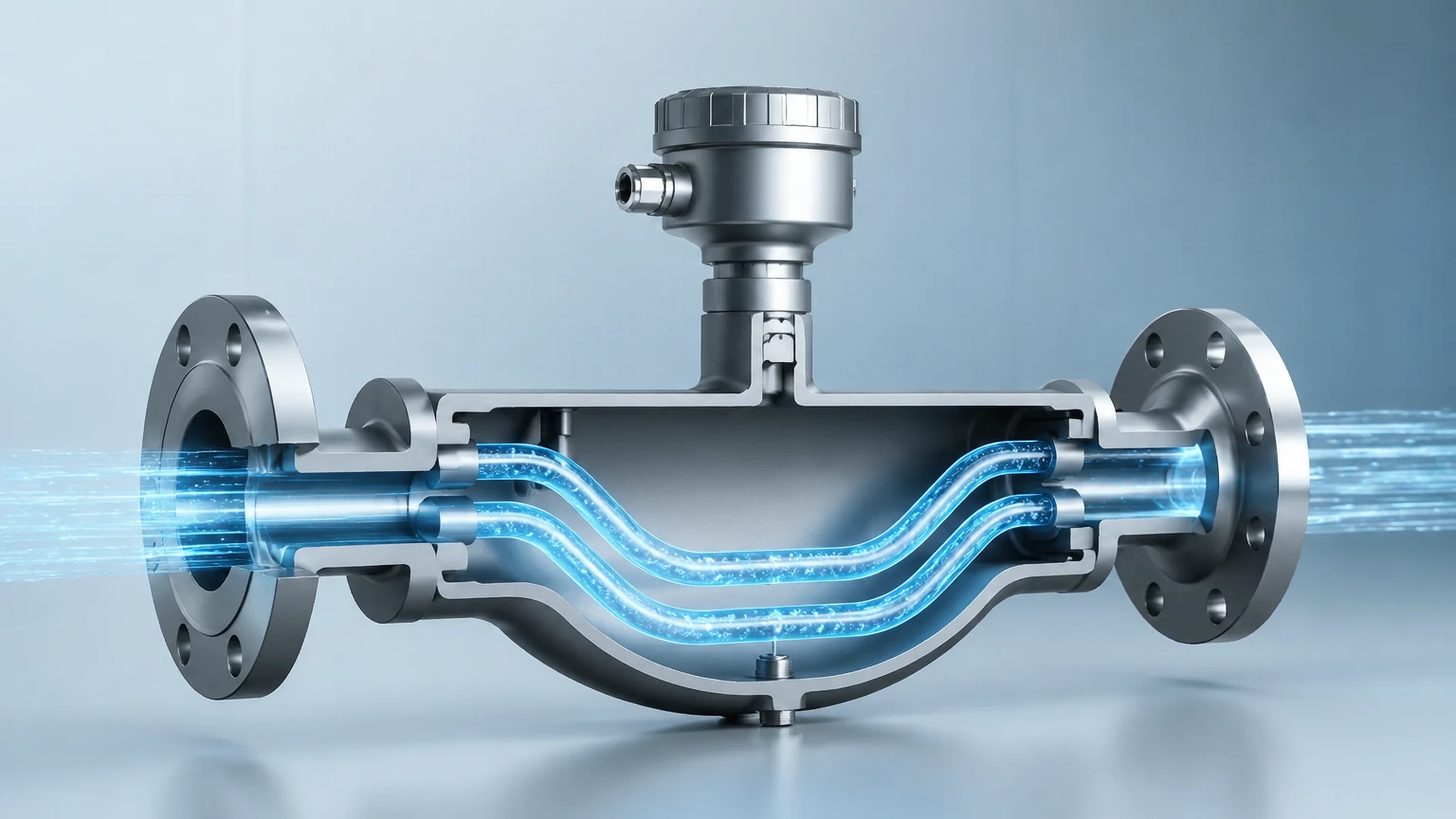
A Coriolis meter consists of two main parts: the sensor (the wetted part in the pipeline) and the transmitter (the electronics that process the signal). Inside the sensor housing, the following components are critical to the measurement process:
1. Measuring Tubes: These can be single or dual tubes, often shaped like a "U," a triangle, or a straight line. Dual-tube designs are common because they are easier to isolate from external pipeline vibrations.
2. Drive Coil: This electromagnetic component causes the tubes to vibrate at their natural resonant frequency, similar to a tuning fork.
3. Pick-off Sensors: Usually located at the inlet and outlet of the measuring tube, these sensors detect the motion of the tube over time.
4. Temperature Sensor: A Resistance Temperature Detector (RTD) is typically integrated to measure the tube temperature, allowing the electronics to compensate for changes in the tube's elasticity caused by thermal fluctuations.
Measuring Mass Flow vs. Volume Flow
The primary advantage of the Coriolis principle is its ability to measure mass directly. Most flow technologies, such as ultrasonic or turbine meters, measure velocity. To convert velocity to mass, the system must know the fluid's density, which changes with temperature and pressure.
The Phase Shift Principle
When there is no flow, the inlet and outlet sides of the vibrating tube move in synchronization. However, when fluid begins to flow, the Coriolis force induces a "twist." This twist causes the inlet side of the tube to lag behind the vibration of the outlet side. This time difference is known as the phase shift.
The electronics measure this phase shift in microseconds. Because the phase shift is directly proportional to the mass flow rate, the meter can provide an exceptionally accurate reading (often within ±0.05% to ±0.1% of the flow rate) regardless of the fluid’s physical properties.
Density and Temperature Measurement Capabilities
Beyond mass flow, Coriolis meters are multi-variable instruments. They provide real-time density and temperature data, which can be used to calculate volume flow or identify changes in fluid composition.
* Density Measurement: The tubes vibrate at their resonant frequency. This frequency is determined by the mass of the tube and the mass of the fluid inside it. If the fluid density increases, the total mass of the vibrating system increases, and the resonant frequency decreases. By measuring the vibration frequency, the meter calculates the fluid density with high precision.
* Temperature Measurement: Since the stiffness of the metal tubes changes with temperature, the integrated RTD ensures that the mass flow and density calculations remain accurate across a wide operating range, typically from -200°C to +350°C (-328°F to +662°F).
Selection Criteria and Application Suitability
When evaluating how a coriolis meter works for a specific project, it is helpful to compare it against other common technologies. While Coriolis meters are highly accurate, they are not always the optimal choice for every application due to cost and pressure drop considerations.
Comparison Table: Coriolis vs. Alternative Technologies
| Feature | Coriolis Meter | Ultrasonic (Transit Time) | Radar (Level/Interface) |
| :— | :— | :— | :— |
| Primary Measurement | Mass Flow & Density | Volumetric Flow | Level / Distance |
| Accuracy | Highest (0.05% – 0.1%) | Moderate (0.5% – 1.0%) | High (1mm – 3mm) |
| Fluid Types | Liquids, Gases, Slurries | Clean Liquids/Gases | Liquids, Solids, Slurries |
| Pressure Drop | Moderate to High | Negligible | None (Non-contact) |
| Initial Cost | High | Moderate | Moderate to High |
| Installation | Rigid mounting required | Pipe run requirements | Top-down mounting |
Coriolis meters are preferred in industries such as oil and gas (for custody transfer), food and beverage (for precise batching), and chemical processing (where density measurement is critical for quality control). For broader industrial automation and inventory management, reviewing various Main Page options for level and flow instrumentation is recommended to ensure the right technology is matched to the specific process environment.
Installation Requirements for Precision
To maintain the high accuracy inherent in the Coriolis design, several installation factors must be addressed. Because the meter relies on sensing minute vibrations and phase shifts, external mechanical noise can interfere with the signal.
1. Rigid Mounting: The meter should be securely supported. The piping on either side of the meter should be anchored to prevent pipeline vibrations from reaching the sensor tubes.
2. Zero Calibration: After installation and under full-pipe, no-flow conditions, a "zero trim" must be performed. This accounts for the specific mechanical stresses of the installation.
3. Orientation:
* Liquids: The meter should ideally be installed in a "U-tube down" position or in a vertical line with upward flow to prevent air bubbles from being trapped in the tubes.
* Gases: The meter should be installed in a "U-tube up" position or in a vertical line with downward flow to prevent condensate from accumulating.
4. Avoid Cavitation: Ensure the downstream pressure is high enough to prevent the fluid from flashing or cavitating inside the meter, which would cause significant measurement errors.
Limitations and Operational Constraints
While highly versatile, Coriolis meters have specific limitations that engineers must account for during the design phase:
* Pressure Drop: The flow must be diverted through the measuring tubes, which are often narrower than the process piping. This creates a pressure drop that must be calculated, especially for high-viscosity fluids.
* Entrained Air: Large amounts of air or gas bubbles in a liquid stream can dampen the tube vibration, leading to a "stalling" of the electronics or significant inaccuracies. While modern digital signal processing (DSP) can handle some entrained air, it remains a challenge.
* Size and Weight: Coriolis meters for large pipe diameters (above 10 inches or 250mm) are extremely heavy and expensive compared to magnetic or ultrasonic alternatives.
* Cost: The initial investment for a Coriolis meter is typically higher than for most other flow technologies. However, the total cost of ownership is often lower due to reduced maintenance and the elimination of secondary density/temperature transmitters.
Frequently Asked Questions (FAQ)
Q: Can a Coriolis meter measure gas flow?
A: Yes. Coriolis meters are effective for gas measurement, though the lower density of gas results in a smaller phase shift, which may require higher flow velocities to maintain accuracy compared to liquid applications.
Q: Does the viscosity of the fluid affect the accuracy?
A: Generally, no. The Coriolis effect is independent of Reynolds number and viscosity. However, extremely high-viscosity fluids will cause a higher pressure drop across the meter.
Q: How often does a Coriolis meter need recalibration?
A: Because there are no moving parts to wear out (like bearings in a turbine meter), Coriolis meters are exceptionally stable. Recalibration intervals are usually determined by industry regulations or internal quality standards rather than sensor drift.
Q: Is a straight-run of pipe required before the meter?
A: Unlike most other flow meters, Coriolis meters do not require long straight runs of pipe upstream or downstream. The measurement happens inside the vibrating tubes, making them ideal for compact skids and tight installations.
Conclusion
Understanding how a coriolis meter works provides the technical foundation for achieving world-class measurement accuracy in industrial processes. By leveraging the Coriolis force to measure mass directly, these instruments bypass the variables of temperature and pressure that complicate other technologies. When correctly selected and installed, they serve as a reliable, multi-variable solution for the most demanding flow and density applications. For professionals seeking comprehensive measurement solutions, including radar and ultrasonic level sensors that complement flow systems, visiting the Main Page of a specialized manufacturer like Welk provides access to the necessary tools for complex system integration.