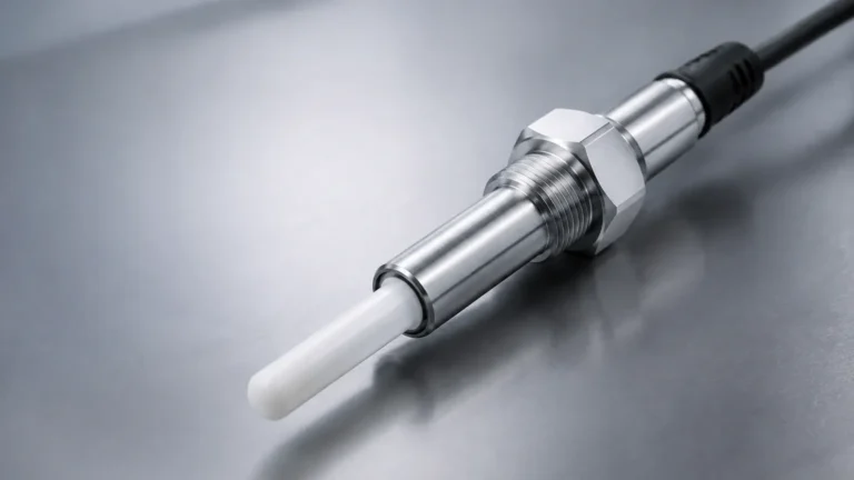
Rtd Temperature Transmitter
Rtd Temperature Transmitter
In the landscape of industrial process control, the accurate measurement of temperature is as fundamental as the measurement of pressure or flow. Among the various technologies available, the Resistance Temperature Detector (RTD) stands out for its high accuracy, stability, and repeatability. However, a raw RTD sensor provides a resistance signal that is susceptible to electrical noise and signal degradation over long distances. This is where the rtd temperature transmitter becomes an essential component. By converting the sensitive resistance signal into a robust, standardized electrical output, these devices ensure that critical temperature data reaches control systems without interference.
For engineers and technicians involved in industrial automation and level measurement, understanding the nuances of transmitter selection and integration is vital. This guide explores the principles, configurations, and practical applications of RTD transmitters within modern process environments.
Understanding the RTD Temperature Transmitter Principle
To appreciate the function of an rtd temperature transmitter, one must first understand the underlying physics of the RTD sensor itself. An RTD operates on the principle that the electrical resistance of a metal increases predictably as its temperature rises. This relationship is known as the temperature coefficient of resistance. Platinum is the most common material used due to its chemical inertness and linear resistance-temperature relationship, leading to the industry-standard Pt100 (100 ohms at 0°C) and Pt1000 sensors.
The role of the transmitter is to interface with this resistive element. It provides a small, constant excitation current to the RTD and measures the resulting voltage drop across the sensor. This voltage is then linearized and converted into a standard industrial signal, typically a 4-20 mA current loop.
Why Use a Transmitter Instead of Direct Wiring?
Directly connecting an RTD to a PLC or DCS over long distances introduces several problems:
1. Lead Wire Resistance: The resistance of the copper wires used for connection adds to the sensor's resistance, causing a positive temperature offset (error).
2. Electromagnetic Interference (EMI): Low-voltage resistance signals are highly susceptible to noise from motors, heavy machinery, and power lines.
3. Signal Strength: Resistance signals do not travel well over hundreds of meters without significant degradation.
A transmitter, usually mounted close to the sensor, solves these issues by converting the signal early in the loop. The 4-20 mA output is immune to lead wire resistance and highly resistant to electrical noise, allowing for reliable data transmission over long distances.
Types of RTD Sensors and Wiring Configurations
The performance of an rtd temperature transmitter is heavily influenced by the wiring configuration of the sensor it is paired with. There are three primary configurations used in industrial settings:
2-Wire Configuration
This is the simplest but least accurate method. It uses two wires to connect the RTD to the transmitter. Since the transmitter cannot distinguish between the resistance of the sensor and the resistance of the lead wires, any change in wire length or temperature will result in a measurement error. This is generally only used when the transmitter is mounted directly to the sensor head with very short leads.
3-Wire Configuration
This is the most common configuration in industrial applications. It uses a third wire to compensate for lead wire resistance. The transmitter assumes that all three wires have identical resistance and uses a bridge circuit or digital calculation to subtract the lead resistance from the total measured resistance. This provides a significant improvement in accuracy over 2-wire setups.
4-Wire Configuration
For laboratory-grade precision or high-accuracy industrial processes, 4-wire RTDs are used. This configuration uses two wires to provide the excitation current and two separate wires to measure the voltage drop. This completely eliminates the effect of lead wire resistance, as no current flows through the measurement wires, resulting in zero voltage drop across them. High-end rtd temperature transmitter units are designed to support 4-wire inputs to maximize measurement integrity.
Key Components and Functions of the Transmitter
A modern industrial transmitter is more than just a signal converter; it is a sophisticated signal processor. Key functions include:
* Signal Linearization: RTDs are nearly linear, but not perfectly so. The transmitter uses internal algorithms (such as the Callendar-Van Dusen equation) to ensure the output signal accurately reflects the temperature across the entire range.
* Isolation: Galvanic isolation protects the control system from high-voltage surges and eliminates ground loops that can cause signal instability.
* Diagnostics: Smart transmitters can detect sensor failures, such as open circuits or short circuits, and drive the output to a specific "fail-safe" level (e.g., 3.5 mA or 21 mA) to alert the operator.
* Communication Protocols: Beyond the standard 4-20 mA signal, many transmitters support HART (Highway Addressable Remote Transducer), which allows digital configuration and diagnostic data to be superimposed on the analog loop.
Selection Criteria for Industrial Applications
Choosing the right rtd temperature transmitter requires a detailed analysis of the process requirements. The following table provides a comparison of common transmitter formats:
| Feature | Head-Mount Transmitter | DIN Rail Transmitter | Field-Mount (Ex d/Ex i) |
| :— | :— | :— | :— |
| Installation Location | Inside the sensor connection head. | Inside a control cabinet or junction box. | Directly in the process area (harsh environments). |
| Space Efficiency | High; requires no extra cabinet space. | Low; occupies DIN rail space. | Moderate; bulky housing. |
| Maintenance | Requires access to the sensor location. | Easy access within the control room. | Access required at the process point. |
| Protection | Dependent on the sensor head (IP65/67). | Standard IP20 (requires enclosure). | High (Explosion-proof/Flameproof). |
| Best For | New installations with integrated sensors. | Centralized monitoring of multiple points. | Hazardous areas and extreme weather. |
Environmental Considerations
When selecting a transmitter, consider the ambient temperature limits of the electronics. Most industrial transmitters are rated for operation between -40°C and +85°C. For applications involving extreme vibration, such as on large pumps or compressors, epoxy-potted head-mount transmitters are preferred to prevent component fatigue.
Installation and Maintenance Best Practices
To ensure the longevity and accuracy of an rtd temperature transmitter, follow these engineering guidelines:
1. Proper Grounding: Ensure the transmitter housing is grounded according to local codes, but avoid multiple ground points on the signal loop to prevent ground loops.
2. Thermowell Selection: In high-pressure or corrosive fluid applications, always use a thermowell. This allows the RTD and transmitter to be removed for calibration without breaking the process seal.
3. Cable Shielding: Use twisted-pair shielded cable for the 4-20 mA loop. The shield should be grounded at only one end (usually the control system end) to drain induced noise.
4. Calibration: Periodic loop calibration is necessary. While the transmitter itself is stable, the RTD sensor can drift over time due to mechanical stress or thermal cycling. Use a dry-block calibrator or a precision resistance decade box to verify the transmitter's output against known inputs.

The Role of Temperature Measurement in Level Instrumentation
In the context of industrial measurement solutions provided by manufacturers like Welk, temperature measurement is often a critical secondary variable for accurate level sensing.
Density Compensation in Hydrostatic Level
Hydrostatic level transmitters measure the pressure exerted by a liquid column. However, the density of a liquid changes with temperature. For example, as oil heats up, it expands and its density decreases. If the temperature is not monitored by an rtd temperature transmitter, the level reading will be inaccurate because the pressure sensor cannot distinguish between a change in height and a change in density. By integrating temperature data, the control system can calculate the true compensated level.
Radar and Ultrasonic Accuracy
While radar level meters are largely unaffected by gas phase temperature, ultrasonic sensors are highly sensitive to it. The speed of sound in air changes by approximately 0.17% per degree Celsius. Without accurate temperature compensation at the transducer face, an ultrasonic level sensor can experience significant errors. In many advanced systems, an external RTD transmitter provides the precise ambient temperature data required for these calculations.
Limitations and Challenges
Despite their reliability, RTD systems have limitations that engineers must manage:
* Self-Heating: The excitation current provided by the transmitter generates a small amount of heat in the RTD element. If the current is too high or the process medium has low thermal conductivity (like stagnant air), this can cause a false high temperature reading. Quality transmitters use very low excitation currents (typically <1 mA) to minimize this effect.
* Response Time: RTDs are generally slower to respond to temperature changes than thermocouples, primarily due to the mass of the platinum element and the protective sheathing. This must be accounted for in fast-moving thermal processes.
* Vibration Sensitivity: The fine platinum wire in an RTD can be fragile. In high-vibration environments, specialized "vibration-resistant" RTD constructions should be used in conjunction with the transmitter.
Frequently Asked Questions (FAQs)
Q: Can I use an RTD transmitter with a thermocouple sensor?
A: Generally, no. RTD transmitters are designed to measure resistance, while thermocouple transmitters measure millivolts. However, some "universal" transmitters are software-configurable to accept either input type.
Q: What is the difference between Pt100 and Pt1000?
A: A Pt100 sensor has a resistance of 100 ohms at 0°C, while a Pt1000 has 1000 ohms. Pt1000 sensors are often used in battery-powered or low-power applications because the higher resistance allows for lower excitation currents, and they are less sensitive to lead wire resistance in 2-wire setups.
Q: How far can I run the 4-20 mA signal from the transmitter?
A: The distance is limited by the loop power supply voltage and the total resistance (load) of the wire and receiving equipment. With a standard 24V DC supply, distances of 1,000 meters or more are common using standard 18 AWG twisted-pair wire.
Q: Does the transmitter need a separate power supply?
A: Most industrial rtd temperature transmitter units are "loop-powered," meaning they draw the small amount of power they need to operate directly from the 4-20 mA current loop. This simplifies wiring significantly.
Conclusion
The rtd temperature transmitter is a cornerstone of precise process monitoring. By bridging the gap between sensitive resistance elements and robust industrial control systems, it ensures that temperature data remains accurate and actionable. Whether used as a standalone measurement point or as a compensation tool for sophisticated level measurement systems, selecting the correct transmitter configuration is essential for operational efficiency. For those seeking comprehensive measurement solutions, reviewing the latest advancements in sensor technology and transmitter integration is the first step toward a more reliable process. For more information on integrated measurement solutions, you can Review product options and application support to find the right fit for your specific industrial needs.