Rtd Transmitters
Rtd Transmitters
In industrial process control, accurate temperature measurement is as critical as pressure or level monitoring. Resistance Temperature Detectors (RTDs) are the industry standard for high-accuracy temperature sensing, but the raw signal from an RTD is a small change in resistance that is susceptible to electrical noise and signal degradation over long distances. This is where rtd transmitters become essential. These devices convert the variable resistance of an RTD sensor into a robust, standardized signal—typically 4-20 mA, HART, or a digital fieldbus protocol—ensuring data integrity between the point of measurement and the control system.
For engineers managing complex liquid storage or chemical processing, temperature data is rarely an isolated variable. It is a fundamental component of accurate level measurement. Whether adjusting for density changes in hydrostatic tanks or compensating for the speed of sound in ultrasonic level applications, integrating reliable temperature transmitters is a prerequisite for process safety and efficiency. This guide explores the principles, selection criteria, and practical applications of these instruments within the broader context of industrial automation.
Measurement Principles of RTD Transmitters
To understand how a transmitter functions, one must first understand the sensor it supports. An RTD operates on the principle that the electrical resistance of a metal increases as its temperature rises. Most industrial RTDs are made of platinum (Pt), with the Pt100 (100 ohms at 0°C) and Pt1000 (1000 ohms at 0°C) being the most common configurations.
Signal Conversion
The primary role of rtd transmitters is to provide excitation current to the RTD element, measure the resulting voltage drop, and translate that resistance value into a linear output. Because the relationship between platinum resistance and temperature is well-defined (governed by the Callendar-Van Dusen equation), the transmitter can calculate the temperature with high precision.
Lead Wire Compensation
A significant challenge in resistance measurement is the resistance of the lead wires connecting the sensor to the electronics. If not accounted for, this added resistance is interpreted as a higher temperature, leading to errors. Transmitters handle this through different wiring configurations:
* 2-Wire: No compensation for lead resistance. Best for short distances or applications where high accuracy is not required.
* 3-Wire: The most common industrial standard. It uses a third wire to measure lead resistance and subtract it from the total, assuming all wires have equal resistance.
* 4-Wire: The most accurate method. It uses two wires to carry the excitation current and two independent wires to measure the voltage across the RTD, completely eliminating the effect of lead wire resistance.
The Role of Temperature in Level Measurement
While rtd transmitters are standalone temperature tools, they are frequently paired with level measurement systems provided by manufacturers like Welk. In many industrial scenarios, level and temperature are interdependent variables.
Hydrostatic Pressure Compensation
Hydrostatic level sensors measure the pressure exerted by a liquid column. However, pressure is a function of both height and density. Since liquid density changes with temperature, a hydrostatic system requires real-time temperature data via an RTD to calculate the true level accurately. Without this compensation, a 10°C shift in temperature could result in a significant volume error in large storage tanks.
Ultrasonic and Radar Applications
In ultrasonic level measurement, the sensor calculates distance based on the time it takes for a sound wave to travel to the surface and back. The speed of sound varies significantly with air temperature. Most high-end ultrasonic transmitters include an integrated RTD or an input for external rtd transmitters to adjust the calculation in real-time. Similarly, while radar (EM waves) is less affected by temperature than ultrasonic (mechanical waves), extreme temperature fluctuations can still affect the dielectric properties of certain vapors, requiring monitoring for high-precision mass balance calculations.
Types of RTD Transmitters and Mounting Options
Selecting the right transmitter involves choosing a form factor that fits the physical environment and the wiring architecture of the plant.
| Transmitter Type | Mounting Location | Best Use Case | Pros | Cons |
| :— | :— | :— | :— | :— |
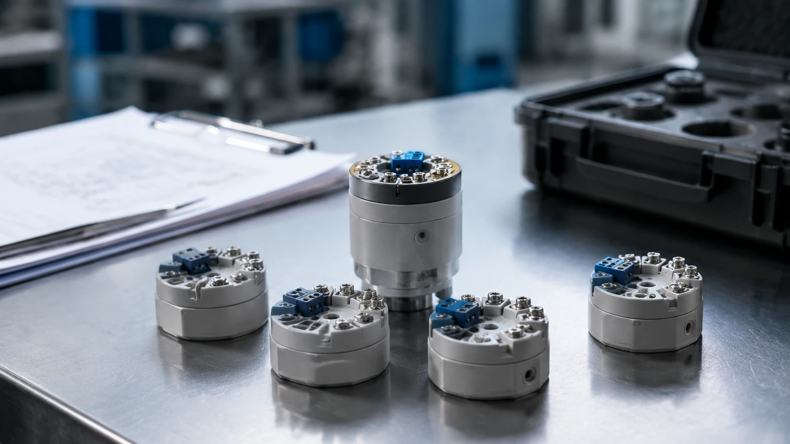
| Head-Mount | Inside the sensor connection head | Direct sensor integration | Compact, reduces wiring noise | Difficult to access for maintenance in high-heat areas |
| DIN Rail Mount | Inside a control cabinet or junction box | Centralized monitoring | Easy maintenance, protected environment | Requires long runs of sensor-level wiring |
| Field-Mount | Rugged external housing near the sensor | Harsh outdoor or corrosive environments | Highly durable, local displays often included | Higher initial cost |
| Integrated | Built into a multi-variable sensor | Level/Temp combined probes | Simplified installation, single cable | If one component fails, the entire unit may need replacement |
|
Technical Selection Criteria
When specifying rtd transmitters, engineers must evaluate several technical parameters to ensure the device meets the demands of the process.
1. Input Compatibility: Ensure the transmitter supports the specific RTD type (e.g., Pt100, Pt500, Pt1000) and the wiring configuration (3-wire vs. 4-wire).
2. Output Signal: While 4-20 mA is the standard, many modern facilities require HART (Highway Addressable Remote Transducer) protocol for remote configuration and diagnostics. For digital-first plants, Profibus or Foundation Fieldbus may be necessary.
3. Accuracy and Stability: Look for the "interchangeability" or "class" of the transmitter. High-precision applications require transmitters with low drift (less than 0.05% of span per year) and high ambient temperature rejection.
4. Galvanic Isolation: This protects the control system from electrical surges and eliminates ground loops, which are common in large industrial sites with multiple grounded points.
5. Environmental Ratings: For chemical or oil and gas applications, transmitters often require ATEX or IECEx certification for explosive atmospheres, as well as IP67 or NEMA 4X ratings for moisture protection.
Installation Considerations and Best Practices
Proper installation is critical to maintaining the accuracy of rtd transmitters. Even the most expensive instrument will provide false data if installed incorrectly.
* Thermowell Placement: The RTD probe should be immersed deep enough into the process fluid to avoid "stem conduction" error, where heat travels up the sensor shaft to the cooler ambient air. A general rule is an immersion depth of at least 10 times the diameter of the protection tube.
* Shielding and Grounding: Always use shielded twisted-pair cables for the 4-20 mA loop to prevent EMI (Electromagnetic Interference) from motors and variable frequency drives (VFDs). The shield should be grounded at one end only (usually the control room side) to prevent ground loops.
* Calibration: While rtd transmitters are more stable than thermocouples, they still require periodic verification. Perform a "loop calibration" by checking the sensor, transmitter, and PLC display as a single system using a dry-block calibrator or a precision resistance decade box.
Limitations and Common Risks
Despite their reliability, rtd transmitters have limitations that must be managed:
* Self-Heating: The transmitter must pass a small current through the RTD to measure resistance. This current generates a tiny amount of heat. If the excitation current is too high, it can artificially raise the sensor's temperature reading, especially in stagnant fluids or gases.
* Response Time: RTDs are generally slower to respond to rapid temperature changes than thermocouples due to the mass of the platinum element and the protective sheathing. In high-speed thermal cycling processes, this lag must be accounted for in the control logic.
* Vibration: RTD elements are made of fine wire or thin films. In high-vibration environments (e.g., near large pumps), the element can fracture. In such cases, vibration-resistant RTDs or remote-mounted DIN rail transmitters are preferred over head-mounted units.
Frequently Asked Questions (FAQs)
Q: Can I use a Pt1000 sensor with a transmitter designed for Pt100?
A: Generally, no. The transmitter's internal electronics are scaled for a specific resistance range. However, many modern "universal" rtd transmitters are software-configurable and can be switched between Pt100, Pt1000, and even various thermocouple types.
Q: What is the maximum distance I can run wires between the RTD and the transmitter?
A: For a 3-wire system, you can typically run up to 30 meters (approx. 100 feet) without significant error, provided the wires are of equal length and gauge. For longer distances, it is highly recommended to use a head-mount transmitter to convert the signal to 4-20 mA immediately at the source, as the current loop can travel hundreds of meters without loss.
Q: Why use a transmitter instead of wiring the RTD directly to a PLC?
A: While some PLCs have RTD input cards, using a dedicated transmitter provides better isolation, local signal conditioning, and the ability to use standard analog input cards which are often cheaper and more versatile. Transmitters also allow for easier field diagnostics.
Q: How do I know if my transmitter has failed or if it is the sensor?
A: Most smart rtd transmitters feature sensor break detection. If the RTD wire snaps, the transmitter will drive the output signal to a specific "upscale" (e.g., 21.5 mA) or "downscale" (e.g., 3.5 mA) value to alert the operator of a hardware fault rather than a process temperature issue.
For further technical specifications on integrated measurement solutions, you may Review product options and application support to see how temperature and level technologies are combined in professional industrial environments. Understanding the synergy between these variables is the key to robust process automation and reliable inventory management.