Water Flow Sensor Ultrasonic
Water Flow Sensor Ultrasonic
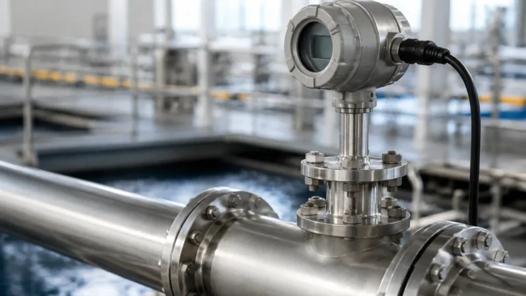
In modern industrial automation and water management, the transition from mechanical flow meters to electronic sensing has significantly improved reliability and reduced maintenance overhead. A water flow sensor ultrasonic utilizes high-frequency sound waves to determine the velocity of a liquid within a pipe or open channel. Unlike traditional turbine or displacement meters, ultrasonic sensors often feature a non-invasive design, meaning they have no moving parts to wear out or obstruct the flow path.
For process engineers and facility managers, understanding the technical nuances of these sensors is critical for ensuring long-term accuracy in water treatment, chemical processing, and industrial cooling systems. This guide examines the measurement principles, selection criteria, and installation requirements for ultrasonic flow technology.
Understanding Ultrasonic Flow Measurement Principles
Ultrasonic flow measurement is primarily categorized into two distinct methods: Transit-Time and Doppler Effect. The choice between these depends largely on the characteristics of the water being measured.
Transit-Time Method
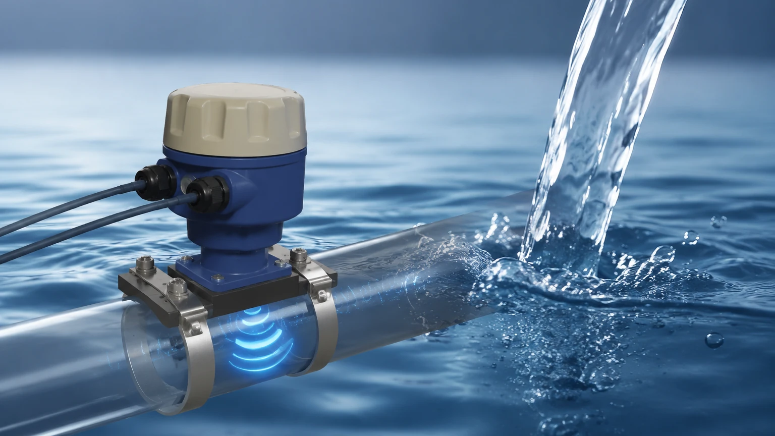
Transit-time sensors are the most common choice for clean water applications. This technology utilizes a pair of transducers, each acting as both a transmitter and a receiver. One transducer sends a sound pulse downstream, while the other sends a pulse upstream.
Because the moving water carries the sound waves, the pulse traveling downstream reaches the opposite transducer faster than the pulse traveling upstream. The difference in these travel times (the "transit time") is directly proportional to the flow velocity.
* Formula Concept: $v = K \cdot \Delta t / (t_{up} \cdot t_{down})$, where $v$ is velocity, $K$ is a calibration constant, and $\Delta t$ is the time difference.
* Requirement: The liquid must be relatively clear of solids and air bubbles (typically less than 2% by volume) to allow the sound pulses to pass through without excessive scattering.
Doppler Effect Method
Doppler sensors are designed for "dirty" water or slurries. This method relies on the reflection of sound waves off particles or entrained air bubbles in the moving fluid. The sensor transmits a continuous high-frequency sound; when this sound hits a moving particle, it reflects back to the receiver at a shifted frequency. This frequency shift (the Doppler shift) is proportional to the speed of the particles, and thus the speed of the water.
* Requirement: The fluid must contain a minimum concentration of suspended solids or bubbles (usually >100 ppm) to provide enough reflective surfaces for the signal.
Types of Ultrasonic Water Flow Sensors
Depending on the application environment and pipe configuration, ultrasonic sensors are available in several physical formats. For a detailed look at specific instrument models and technical data sheets, professionals often refer to the Main Page of industrial equipment providers to match sensor specs with project requirements.
1. Clamp-On Sensors
Clamp-on ultrasonic flow meters are mounted on the exterior of the pipe. They are highly valued for retrofit applications because they do not require cutting the pipe or shutting down the process. They eliminate the risk of leaks and pressure drops.
2. Inline (Wetted) Sensors
Inline sensors are integrated into a pipe section (spool piece) with the transducers pre-mounted in contact with the fluid. These are generally more accurate than clamp-on models because the path length and transducer alignment are factory-calibrated and fixed. They are preferred for high-precision billing or custody transfer applications.
3. Open Channel Flow Sensors
In wastewater treatment and irrigation, water often flows in open channels rather than pressurized pipes. In these cases, an ultrasonic level sensor is paired with a primary device like a flume or weir. The sensor measures the height (head) of the water, and the flow rate is calculated based on the known geometry of the channel. As a professional manufacturer, Welk provides specialized ultrasonic level transmitters that are frequently adapted for these open-channel flow calculations.
Key Selection Criteria for Industrial Applications
Selecting the correct water flow sensor ultrasonic requires an evaluation of both the fluid properties and the physical environment. The following table provides a comparison of typical performance metrics for industrial-grade units.
| Feature | Transit-Time (Clean Water) | Doppler (Dirty Water) | Open Channel (Ultrasonic Level) |
| :— | :— | :— | :— |
| Typical Accuracy | ±0.5% to ±1.0% of rate | ±2.0% to ±5.0% of rate | ±2.0% to ±5.0% of system |
| Pipe Size Range | 10 mm to 5000 mm | 25 mm to 3000 mm | N/A (Channel width dependent) |
| Fluid Velocity | 0.1 to 12 m/s | 0.2 to 10 m/s | 0.05 to 5 m/s |
| Solids Content | < 2% (by volume) | > 100 ppm | Variable |
| Installation Cost | Low (Clamp-on) to Mid | Low (Clamp-on) | Mid (Requires Flume/Weir) |
Fluid Temperature and Pressure
Standard ultrasonic transducers typically operate between -20°C and +150°C. High-temperature variants are available for steam condensate or hot water loops, but they require specialized coupling compounds or high-temperature wedges. Pressure is generally not a limiting factor for clamp-on sensors, as they do not penetrate the pipe wall, but inline models must be rated for the specific process pressure (e.g., PN16, PN40).
Installation Best Practices and Straight Pipe Requirements
The accuracy of a water flow sensor ultrasonic is heavily dependent on the flow profile. Turbulence caused by elbows, valves, or pumps can lead to significant measurement errors.
1. Straight Run Requirements: To ensure a fully developed laminar flow profile, sensors should ideally be installed with a straight pipe run of at least 10 diameters (10D) upstream and 5 diameters (5D) downstream from any obstruction. For example, if the pipe diameter is 100 mm, provide 1000 mm of straight pipe before the sensor.
2. Pipe Orientation: For horizontal pipes, transducers should be mounted at the 3 o'clock and 9 o'clock positions. Mounting them at the top (12 o'clock) risks interference from air pockets, while the bottom (6 o'clock) is prone to interference from sediment buildup.
3. Full Pipe Condition: Ultrasonic meters (except for specific open-channel configurations) require a full pipe to function correctly. In vertical installations, the flow should always be upward to ensure the pipe remains filled and air bubbles are carried away.
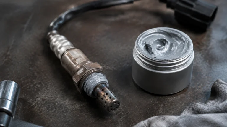
4. Coupling Agents (Clamp-on): For clamp-on models, an acoustic coupling grease or pad must be used between the transducer face and the pipe wall to eliminate air gaps. Air is a poor conductor of high-frequency sound and will block the signal entirely.
Limitations and Operational Risks
While ultrasonic technology is robust, engineers must be aware of specific limitations that can affect performance:
* Signal Attenuation: Certain pipe materials, such as old cast iron with heavy internal scaling or cement-lined pipes, can absorb or scatter ultrasonic signals. This makes it difficult for clamp-on sensors to receive a clear pulse.
* Aeration and Bubbles: In transit-time meters, excessive air bubbles (often caused by pumps or chemical reactions) will break the ultrasonic beam, leading to "signal loss" errors.
* Reynolds Number Sensitivity: Ultrasonic meters are sensitive to the Reynolds number, which characterizes the flow as laminar, transitional, or turbulent. Modern digital signal processors (DSP) in sensors like those from Welk automatically compensate for these changes, but extreme low-flow conditions may still see reduced accuracy.
* Ambient Noise: High-frequency mechanical noise from nearby variable frequency drives (VFDs) or heavy machinery can occasionally interfere with the sensor electronics if the cabling is not properly shielded.
Frequently Asked Questions (FAQs)
Q: Can a water flow sensor ultrasonic measure deionized (DI) water?
A: Yes. Transit-time ultrasonic sensors are excellent for DI water because they are non-invasive and do not introduce contaminants or ions into the high-purity stream.
Q: How often does the sensor need calibration?
A: Because there are no moving parts to wear, the electronic calibration of an ultrasonic sensor is very stable. However, in regulated industries, an annual verification or calibration check is recommended to ensure the electronics and transducers haven't drifted due to extreme temperature cycling.
Q: Will it work on plastic pipes?
A: Yes, ultrasonic waves travel well through most plastics, including PVC, PE, and PP. The user must simply ensure the pipe wall thickness is correctly entered into the transmitter's configuration menu.
Q: What happens if the pipe is only half full?
A: A standard transit-time or Doppler pipe sensor will provide an error or highly inaccurate reading if the pipe is not full. For partially filled pipes, an area-velocity flow meter or an open-channel ultrasonic level setup is required.
Summary for Project Engineering
Implementing a water flow sensor ultrasonic involves more than just selecting a part number; it requires a holistic view of the piping system and fluid dynamics. By prioritizing the correct measurement principle—transit-time for clean water and Doppler for solids-bearing water—and adhering to strict installation geometries, facilities can achieve high-precision flow monitoring with minimal maintenance.
For engineers currently designing water treatment or industrial automation systems, reviewing the technical specifications of radar and ultrasonic instruments is a necessary step. Reliable data from the Main Page of professional manufacturers like Welk can provide the necessary documentation for sensor integration, ensuring that the chosen hardware meets the specific environmental and accuracy demands of the project.