Sensor Pressure Transducer
Sensor Pressure Transducer
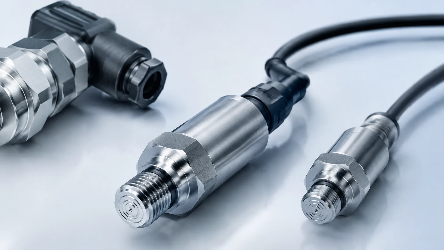
In the landscape of industrial automation and process control, the sensor pressure transducer serves as a fundamental component for monitoring fluid levels, tank volumes, and system pressures. These devices are engineered to convert mechanical force—exerted by a liquid or gas—into a standardized electrical signal. Within the context of level measurement, hydrostatic pressure transducers are particularly prevalent, offering a reliable and cost-effective method for determining the height of a liquid column in both open and closed vessels.
Selecting the correct sensor pressure transducer requires a deep understanding of the underlying physics, the chemical properties of the media being measured, and the environmental conditions of the installation site. This guide provides a technical overview of measurement principles, selection criteria, and practical engineering considerations for integrating these sensors into industrial workflows.
Understanding the Measurement Principle
The operation of a sensor pressure transducer in level measurement applications is based on the principle of hydrostatic pressure. According to Stevin’s Law, the pressure at a specific depth within a static liquid is directly proportional to the height of the liquid column above it, the density of the liquid, and the force of gravity.
The Hydrostatic Equation
The relationship is expressed by the formula:
P = ρ × g × h
Where:
* P is the hydrostatic pressure (measured in Pascals or bar).
* ρ (rho) is the density of the liquid (kg/m³).
* g is the local acceleration due to gravity (approximately 9.81 m/s²).
* h is the height of the liquid column (meters).
By measuring the pressure at the bottom of a tank and knowing the density of the fluid, the control system can accurately calculate the level (h). A sensor pressure transducer typically utilizes a flexible diaphragm that deflects under the weight of the liquid. This deflection is captured by a sensing element—such as a piezoresistive strain gauge or a capacitive sensor—which then modulates an electrical circuit to produce an output signal, commonly 4-20 mA or 0-10 V.
Sensing Technologies
1. Piezoresistive Sensors: These utilize a silicon-based element where the electrical resistance changes as the diaphragm deforms. They are known for high sensitivity and compact size.
2. Ceramic Capacitive Sensors: These use a ceramic diaphragm that forms one plate of a capacitor. As pressure moves the diaphragm, the capacitance changes. These are highly resistant to corrosion and abrasion, making them ideal for harsh chemical environments.
Role of the Sensor Pressure Transducer in Level Measurement
While pressure transducers are used for various tasks, their role in level measurement is distinct. They are often categorized into two main installation types: submersible and externally mounted.
Submersible Transducers
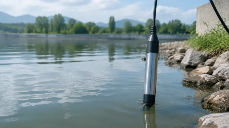
In applications like deep wells, reservoirs, or open-top water treatment tanks, a submersible sensor pressure transducer is lowered directly into the liquid. These units are hermetically sealed and include a vented cable that allows the internal side of the sensor to reference atmospheric pressure, ensuring accurate gauge pressure readings regardless of changes in barometric pressure.
Externally Mounted Transducers
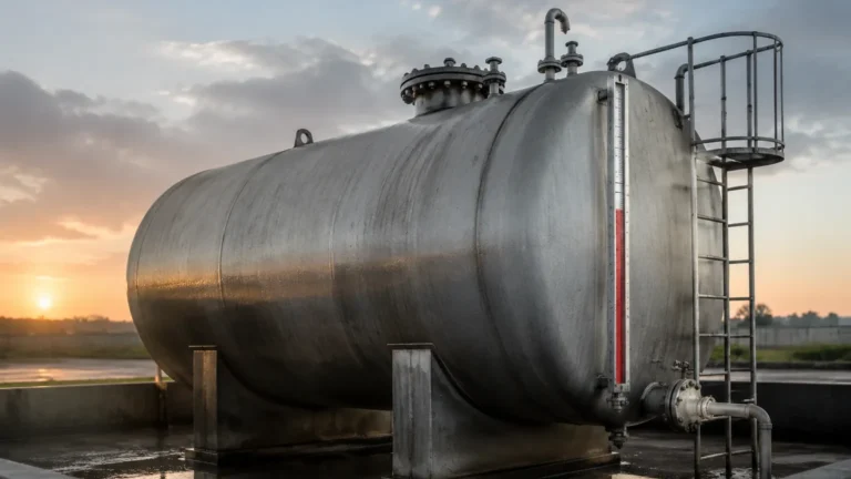
For pressurized tanks or closed vessels, transducers are mounted to the outside of the tank via a flange or threaded connection at the lowest point of measurement. In pressurized environments, a differential pressure (DP) transducer is often required to subtract the overhead gas pressure from the total pressure measured at the bottom, isolating the hydrostatic pressure of the liquid alone.
For engineers evaluating different measurement technologies, including radar and ultrasonic options, it is helpful to consult a comprehensive technical resource. You can review product options and application support on our Main Page.
Key Evaluation Criteria for Selection
Choosing a sensor pressure transducer is not a one-size-fits-all process. Engineers must confirm several technical parameters to ensure long-term reliability and accuracy.
1. Pressure Range and Overpressure Rating
The nominal range of the sensor should be closely matched to the maximum expected liquid height. However, the "overpressure rating" is equally critical. This defines the maximum pressure the sensor can withstand without permanent damage or calibration shift. In systems where water hammer or pump surges occur, a high overpressure safety margin (e.g., 2x or 3x the nominal range) is necessary.
2. Media Compatibility
The wetted materials—those in direct contact with the fluid—must be chemically compatible. While 316L stainless steel is standard for water and light oils, aggressive chemicals like acids or seawater may require specialized materials such as Hastelloy C, Tantalum, or PTFE-coated diaphragms.
3. Accuracy and Thermal Drift
Accuracy is typically expressed as a percentage of Full Scale (FS). This includes errors from linearity, hysteresis, and repeatability. Furthermore, because liquid density and sensor electronics are affected by temperature, the "thermal error band" must be considered. High-quality transducers include internal temperature compensation to minimize drift in outdoor or high-temperature process applications.
4. Signal Output and Communication
While the 4-20 mA analog signal remains the industry standard due to its noise immunity, modern smart transducers often support digital protocols like HART, Modbus RTU (RS485), or Profibus. These protocols allow for remote configuration and diagnostic monitoring.
Practical Selection Table for Industrial Applications
The following table outlines common scenarios and the recommended sensor pressure transducer configurations.
| Application Type | Recommended Sensor Type | Diaphragm Material | Key Consideration |
| :— | :— | :— | :— |
| Clean Water Reservoirs | Submersible Hydrostatic | 316L Stainless Steel | Vented cable for atmospheric compensation. |
| Chemical Storage (Acid) | External Flanged | Ceramic or Tantalum | High corrosion resistance required. |
| Wastewater Sump | Submersible (Clog-resistant) | Large Flush Diaphragm | Resistance to solids and buildup. |
| High-Pressure Boilers | Differential Pressure | 316L or Monel | Must account for high static head pressure. |
| Fuel Oil Tanks | Gauge Pressure Transducer | 316L Stainless Steel | Compatibility with hydrocarbons and seals. |
Installation Guidelines and Best Practices
Correct installation is as important as sensor selection. Even the most accurate sensor pressure transducer will provide faulty data if installed incorrectly.
Positioning and Mounting
* Avoid Turbulence: In tanks with agitators or high-velocity inlets, the sensor should be installed in a stilling well or a shielded area to prevent pressure fluctuations caused by moving fluid.
* Reference Point: The sensor must be located at or below the "zero level" of the tank. Any liquid below the sensor diaphragm will not be measured (the "dead zone").
Cable and Venting Management
For submersible units, the vented cable is the most common point of failure. The vent tube must remain unobstructed and protected from moisture. Using a desiccant cartridge or a specialized vent box at the termination point prevents water vapor from entering the tube, which could lead to internal corrosion or measurement errors.
Electrical Protection
Industrial environments are prone to electrical noise and lightning strikes, especially in outdoor water management. Ensure the sensor is properly grounded and consider using surge protection modules for long cable runs to prevent damage to the sensor pressure transducer electronics.
Common Risks and Limitations
While highly versatile, hydrostatic pressure measurement has inherent limitations that engineers must account for during the design phase.
* Density Fluctuations: Since the calculation of level depends on fluid density (ρ), any change in the liquid's composition or temperature will change its density and, consequently, the pressure reading. If the density varies significantly, a temperature-compensated density correction must be programmed into the PLC/controller.
* Sedimentation and Clogging: In fluids with high solids content, sediment can accumulate on the diaphragm. This increases the perceived weight and leads to a "high" error. Regular cleaning or the use of flush-diaphragm designs can mitigate this risk.
* Mechanical Stress: Excessive vibration from nearby pumps can fatigue the sensing element over time. Mounting the transducer on a vibration-dampened bracket or using capillary tubes to isolate the sensor from the process line can extend its service life.
Frequently Asked Questions (FAQ)
Q: Can a sensor pressure transducer measure the level of a boiling liquid?
A: It is challenging. Boiling liquids have fluctuating densities due to vapor bubbles, and the increased vapor pressure in a closed tank requires a differential pressure setup. Additionally, the temperature must stay within the sensor's compensated operating range.
Q: How often should a hydrostatic level sensor be calibrated?
A: For most industrial applications, an annual calibration check is recommended. However, in critical or high-fouling environments, a six-month interval may be necessary to ensure accuracy hasn't drifted due to diaphragm coating or fatigue.
Q: What is the difference between a pressure sensor and a pressure transducer?
A: In common industrial parlance, the terms are often used interchangeably. Technically, a "sensor" is the raw element that detects the change, while a "transducer" includes the signal conditioning electronics to provide a standardized electrical output (like 4-20mA).
Q: Does the shape of the tank affect the pressure reading?
A: No. Hydrostatic pressure depends only on the height of the liquid and its density, not the volume or shape of the container. A narrow pipe and a wide lake will exert the same pressure at a depth of 10 meters (32.8 feet).
Conclusion
The sensor pressure transducer remains a cornerstone of industrial level measurement due to its simplicity and reliability. By understanding the hydrostatic principle and carefully matching sensor materials and ranges to the specific application, operators can achieve precise control over their processes. Whether monitoring a simple water tank or a complex chemical reactor, the right transducer ensures safety, efficiency, and data integrity. For further technical specifications and to explore our full range of level measurement solutions, please visit our Main Page.