Subsea Pressure Transducers
Subsea Pressure Transducers
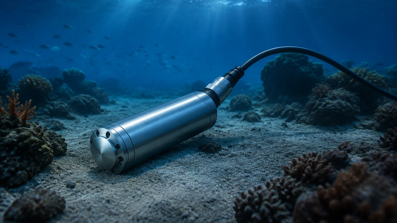
Subsea pressure transducers are specialized sensing devices engineered to withstand the extreme conditions of underwater environments. Unlike standard industrial pressure sensors, these instruments must operate under immense external hydrostatic pressure while resisting the corrosive effects of seawater and the potential for biological fouling. In the fields of offshore oil and gas, marine research, and underwater robotics, subsea pressure transducers serve as the primary means of monitoring process pressures, hydraulic system health, and depth measurement through hydrostatic calculations.
Understanding the engineering behind these devices is essential for selecting the correct instrument for a specific depth and application. This guide examines the measurement principles, material requirements, and selection criteria necessary for deploying reliable subsea instrumentation.
Measurement Principles of Subsea Pressure Transducers
The fundamental operation of a subsea pressure transducer relies on converting mechanical force—exerted by a fluid or the surrounding ocean—into an electrical signal. There are several sensing technologies employed, each with distinct advantages for underwater use.
Piezoresistive Sensing
This is the most common technology for subsea applications. It utilizes a silicon diaphragm with diffused strain gauges. When pressure is applied, the diaphragm deforms, changing the electrical resistance of the gauges. In subsea environments, the silicon element is typically isolated from the seawater by a thin metallic diaphragm (often made of Hastelloy or Titanium) and a fill fluid, such as silicone oil, which transmits the pressure to the sensor.
Thin-Film Strain Gauge
Thin-film sensors involve depositing a resistive material directly onto a stainless steel or nickel-alloy diaphragm using vacuum deposition. These sensors are known for their long-term stability and robustness against pressure spikes and vibrations, making them suitable for subsea hydraulic control modules (SCMs).
Hydrostatic Pressure and Depth Correlation
In subsea applications, pressure transducers are frequently used to determine depth. The relationship is governed by the hydrostatic pressure formula:
$$P = \rho \cdot g \cdot h$$
Where:
* P is the hydrostatic pressure (Pa).
* ρ (rho) is the density of the fluid (approximately 1025 kg/m³ for seawater).
* g is the acceleration due to gravity (9.81 m/s²).
* h is the depth or height of the liquid column (m).
Engineers must account for variations in water density caused by salinity and temperature to ensure accurate depth readings, especially in deep-sea deployments exceeding 1,000 meters.
Key Evaluation Criteria for Selection
Selecting subsea pressure transducers requires a rigorous evaluation of the operating environment and the required data precision. Failure to account for depth-related stresses or chemical compatibility can lead to premature instrument failure.
Pressure Range and Overpressure Ratings
Subsea sensors must handle two types of pressure: the internal process pressure being measured and the external ambient pressure from the sea. For sensors mounted inside a pressure-compensated housing, the differential pressure is the primary concern. However, for sensors exposed directly to the ocean, the housing must be rated for the maximum deployment depth. It is standard practice to select a transducer with a range at least 20% higher than the maximum expected pressure to avoid damage from transient spikes.
Accuracy and Total Error Band (TEB)
Accuracy is usually defined as a percentage of the Full Scale (FS). In subsea engineering, the Total Error Band is a more critical metric, as it includes the effects of temperature linearity, hysteresis, and repeatability over a specific temperature range (e.g., -2°C to +40°C for seawater). High-precision transducers for oceanographic research may offer accuracies of 0.01% FS, while industrial offshore applications typically utilize 0.1% to 0.25% FS.
Material Compatibility
Seawater is a highly corrosive electrolyte. The choice of wetted materials is the most significant factor in the lifespan of subsea pressure transducers. Common materials include:
* 316L Stainless Steel: Suitable for short-term immersion or shallow water with cathodic protection.
* Duplex and Super Duplex Steel: Offers higher resistance to pitting and crevice corrosion.
* Inconel 625/718: Highly resistant to stress corrosion cracking and hydrogen embrittlement, often used in oil and gas.
* Titanium: The gold standard for long-term deep-sea deployment due to its exceptional strength-to-weight ratio and near-immunity to seawater corrosion.
Technical Selection Table
The following table provides a general comparison of subsea pressure transducer specifications based on deployment depth.
| Feature | Shallow Water (0–200m) | Mid-Depth (200–2,000m) | Deep Sea (>2,000m) |
| :— | :— | :— | :— |
| Typical Material | 316L Stainless Steel | Super Duplex / Inconel | Titanium / Monel |
| Pressure Rating | Up to 20 bar | Up to 200 bar | Up to 600+ bar |
| Electrical Interface | 4-20mA / 0-10V | Modbus RTU / CANbus | RS-485 / Ethernet |
| Sealing Method | O-ring / Overmolding | Metal-to-Metal Seal | Glass-to-Metal Header |
| Common Use | Harbor monitoring | ROV / AUVS | Wellhead monitoring |
Installation and Integration Considerations
Proper installation is as critical as the sensor's specifications. In subsea environments, the primary failure points are often the electrical connections and cable entries rather than the sensor element itself.
Subsea Connectors
For deep-water applications, "wet-mateable" connectors allow for connections to be made underwater, though they are significantly more expensive. For most fixed installations, "dry-mateable" connectors are used, which must be joined and sealed on the surface before deployment. These connectors often utilize gold-plated pins to prevent oxidation and ensure signal integrity over long cable runs.
Signal Attenuation and Data Transmission
Analog signals like 4-20mA are robust against noise but can suffer from voltage drops over very long cables (umbilicals). For deep-sea deployments, digital protocols such as RS-485 or CANbus are preferred. These allow for multi-drop configurations where multiple subsea pressure transducers can communicate over a single pair of wires, reducing the weight and cost of the umbilical cable.
Orientation and Bleeding
When installing a transducer to measure process pressure in a subsea manifold, the orientation must prevent the accumulation of silt or gas bubbles against the sensing diaphragm. If gas is trapped, it can act as a damper, leading to sluggish response times or inaccurate readings. Bleeding the system to ensure the sensing cavity is entirely filled with the process fluid or protective oil is a standard commissioning step.
Common Risks and Limitations
Despite advanced engineering, subsea pressure transducers face several environmental risks that can compromise data accuracy or hardware integrity.
1. Biofouling: Marine organisms such as barnacles and algae can grow on the sensor diaphragm. This adds mass and restricts fluid movement, leading to significant measurement drift. Anti-fouling coatings or copper-nickel guards are often used to mitigate this.
2. Hydrogen Embrittlement: In offshore oil and gas, the presence of hydrogen sulfide ($H_2S$) or the use of cathodic protection systems can lead to hydrogen atoms diffusing into the metal of the transducer. This makes the material brittle and prone to cracking. Selecting materials like Inconel 718 is necessary in these "sour" environments.
3. Pressure Hysteresis: After being subjected to the extreme pressures of the deep ocean, some sensors may not return exactly to their zero-point when brought back to the surface. This is known as pressure-induced drift and must be accounted for during recalibration cycles.
4. Thermal Shock: Rapid temperature changes, such as moving a sensor from a warm deck to cold deep-sea water, can cause temporary output fluctuations. High-quality transducers include internal temperature compensation to stabilize the signal during these transitions.
Frequently Asked Questions (FAQs)
Q: What is the difference between a vented and a sealed gauge transducer in subsea use?
A: A vented transducer uses a tube in the cable to reference atmospheric pressure, making it ideal for shallow water depth measurement. However, at great depths, the vent tube is impractical and prone to blockage or moisture ingress. Therefore, deep-sea sensors are almost always "sealed gauge" or "absolute," referencing a vacuum or a fixed internal pressure.
Q: How often should subsea pressure transducers be calibrated?
A: For critical infrastructure like subsea wellheads, calibration is typically checked annually or bi-annually, often through redundant sensor comparisons. For research equipment, calibration is usually performed before and after each deployment mission.
Q: Can these sensors be used in both fresh and saltwater?
A: Yes, but the density constant used to calculate depth must be adjusted. Freshwater has a density of approximately 1,000 kg/m³, whereas seawater is denser (approx. 1,025 kg/m³). Using the wrong constant will result in a depth error of roughly 2.5%.
Conclusion
Subsea pressure transducers are the "eyes" of underwater operations, providing the data necessary for safety, navigation, and process control. By understanding the nuances of material science, hydrostatic principles, and the rigors of the marine environment, engineers can specify instrumentation that ensures long-term reliability. For more comprehensive level measurement solutions and technical support for industrial applications, professionals should consult the Main Page to review product options and application support tailored to complex process requirements.
When planning a subsea deployment, always confirm the maximum operating depth, the chemical composition of the fluid, and the expected duration of immersion. These factors will dictate whether a standard stainless steel sensor is sufficient or if a specialized titanium-housed instrument is required to prevent catastrophic system failure.