Service Flow Meter
Service Flow Meter
In the landscape of industrial automation and process control, the service flow meter stands as a fundamental instrument for monitoring utility fluids and process media. Whether managing water distribution, chemical dosing, or steam consumption, the ability to accurately quantify flow rates is essential for operational efficiency, cost accounting, and safety. While level measurement technologies—such as those found on the Main Page of instrumentation catalogs—provide critical data on volume and inventory, flow meters offer the dynamic perspective of movement within the system.
Selecting the correct service flow meter requires a deep understanding of fluid dynamics, installation constraints, and the specific physical properties of the media being measured. This guide explores the primary measurement principles, selection criteria, and practical engineering considerations for deploying flow meters in industrial environments.
Core Measurement Principles
To select a service flow meter, engineers must first understand the physics governing different measurement technologies. Each principle offers specific advantages depending on the fluid's conductivity, viscosity, and state (liquid, gas, or steam).
Electromagnetic Flow Meters (Magmeters)
Electromagnetic flow meters operate based on Faraday’s Law of Electromagnetic Induction. When a conductive liquid flows through a magnetic field generated by the meter, it induces a voltage proportional to the velocity of the liquid.
* Equation: $E = B \cdot v \cdot D$
* $E$ is the induced voltage.
* $B$ is the magnetic field strength.
* $v$ is the fluid velocity.
* $D$ is the distance between electrodes (pipe diameter).
Magmeters are ideal for water, wastewater, and corrosive chemicals because they have no moving parts and offer no obstruction to the flow, resulting in zero pressure drop. However, they require the fluid to have a minimum conductivity, typically $>5 \mu S/cm$.
Ultrasonic Flow Meters
Ultrasonic meters generally use two methods: Transit Time and Doppler Effect.
1. Transit Time: Two transducers send and receive ultrasonic signals. The signal traveling with the flow moves faster than the signal traveling against it. The time difference is proportional to the flow velocity. This method is best for clean liquids.
2. Doppler Effect: These meters reflect sound waves off bubbles or particles in the fluid. The frequency shift of the reflected signal determines the velocity. This is ideal for slurries or aerated liquids.
Ultrasonic meters are often available in "clamp-on" configurations, allowing for measurement without cutting into the pipe, which is a significant advantage for retrofitting service lines.
Vortex Flow Meters
Vortex meters utilize the Von Kármán effect. As fluid flows past a bluff body (a non-streamlined object) placed in the stream, alternating vortices are shed on downstream sides. The frequency of this vortex shedding is directly proportional to the flow velocity.
These meters are highly versatile and are the preferred choice for measuring saturated or superheated steam and high-temperature gases, where mechanical parts would quickly fail.
Turbine Flow Meters
Turbine meters feature a rotor that spins as fluid passes through it. The rotational speed of the blades is proportional to the flow velocity. These are highly accurate for clean, low-viscosity fluids like fuel oils or deionized water but are susceptible to wear and damage from debris.
Technical Selection Criteria
Choosing a service flow meter is not a one-size-fits-all process. Engineers must evaluate the following parameters to ensure long-term reliability.
Media Characteristics
* Fluid State: Is it a liquid, gas, or steam?
* Conductivity: Essential for electromagnetic meters.
* Viscosity: High-viscosity fluids may require positive displacement or Coriolis meters, as they can cause significant errors in turbine or vortex meters.
* Corrosivity: Determines the material of construction for liners and electrodes (e.g., PTFE, PFA, or Hastelloy).
Process Conditions
* Flow Range (Turndown Ratio): The ratio between the maximum and minimum measurable flow. For example, a meter with a 10:1 turndown and a max flow of 100 $m^3/h$ can accurately measure down to 10 $m^3/h$.
* Pressure and Temperature: Ensure the meter body and sensors are rated for the maximum process limits. Standard industrial meters often handle up to 40 bar (580 psi), but high-pressure applications require specialized flanges.
* Accuracy Requirements: Utility billing usually requires high accuracy (±0.5% or better), whereas simple process indication might only require ±2.0%.
Selection Comparison Table
| Technology | Suitable Media | Accuracy (Typical) | Pressure Drop | Moving Parts | Min. Conductivity Required |
| :— | :— | :— | :— | :— | :— |
| Electromagnetic | Conductive Liquids | ±0.5% | None | No | Yes ( >5 $\mu S/cm$) |
| Ultrasonic | Clean/Dirty Liquids | ±1.0% | None | No | No |
| Vortex | Steam, Gas, Liquid | ±1.0% | Medium | No | No |
| Turbine | Clean Liquids/Gas | ±0.25% | High | Yes | No |
| Differential Pressure | Liquids, Gas, Steam | ±1.0% – 2.0% | High | No | No |
Installation Considerations
Even the most accurate service flow meter will fail to provide reliable data if installed incorrectly. The flow profile must be fully developed and stable for the sensor to read accurately.
Straight Pipe Runs
Most meters require a specific length of straight pipe upstream and downstream to eliminate turbulence caused by elbows, valves, or pumps.
* Upstream: Typically 10 to 20 pipe diameters (10D – 20D).
* Downstream: Typically 5 pipe diameters (5D).
If a 50 mm (2-inch) pipe is used, a 10D requirement means 500 mm of straight pipe must precede the meter.
Orientation and Filling
For liquid service, the pipe must always be completely full.
* Vertical Upward Flow: This is the ideal orientation for liquids as it ensures the pipe remains full and prevents air entrapment.
* Horizontal Flow: The meter should be placed at a low point in the piping. Avoid placing meters at the highest point of a system where air pockets can collect, as this will cause erratic readings or "dry pipe" errors.
Grounding and Interference
Electromagnetic flow meters are sensitive to electrical noise. Proper grounding to the process fluid is mandatory. This is usually achieved via grounding rings or grounding electrodes within the meter. In plastic or lined pipes, grounding rings are essential to provide a reference point for the tiny voltages being measured.
Integration with Level Measurement Systems
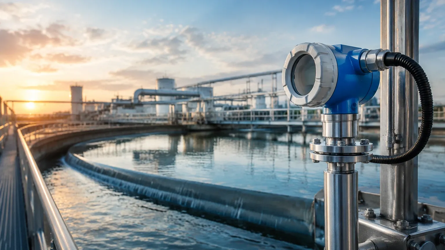
In many industrial applications, flow measurement and level measurement are used in tandem to provide a complete mass balance of a system. For instance, in a chemical storage tank, a radar or ultrasonic level transmitter (available through the Main Page of instrumentation providers) monitors the static inventory. Simultaneously, a service flow meter on the outlet line measures the exact amount of chemical being dosed into the process.
Comparing the "change in level" against the "integrated flow" is a common method for leak detection and pump performance verification. If the level in a tank drops faster than the flow meter indicates, it may signal a leak in the downstream piping or a calibration error in one of the instruments.
Maintenance and Troubleshooting
While modern electronic flow meters are designed for minimal maintenance, service intervals should be established based on the criticality of the measurement.
1. Zero Verification: Periodically check the meter's zero reading under "no-flow" conditions. The pipe must be full and the fluid static.
2. Electrode Cleaning: In magmeters, coating or scaling on the electrodes can insulate them from the fluid, leading to signal loss. Some meters include built-in circuitry to detect electrode coating.
3. Calibration: For regulated industries or billing applications, annual wet calibration or on-site verification using a master meter is recommended.
Common Risks and Limitations
* Cavitation: If the pressure drops too low across a meter (especially turbine or DP meters), vapor bubbles can form and collapse, damaging the internal components and causing significant measurement errors.
* Entrained Air: Air bubbles in a liquid line will cause most flow meters to over-read or fail entirely. Use air eliminators upstream if the process is prone to aeration.
* Reynolds Number Limits: Vortex and some ultrasonic meters require a minimum Reynolds number (typically >10,000 to 20,000) to maintain accuracy. At low flow rates (laminar flow), these meters may become non-linear.
Frequently Asked Questions (FAQ)
Q: Can I use an electromagnetic flow meter for deionized water?
A: Generally, no. Deionized water has very low conductivity, often below the threshold required for a magmeter to detect a signal. An ultrasonic or turbine meter is a better choice for this application.
Q: How do I measure flow in a pipe that is only partially full?
A: Standard flow meters require a full pipe. For partially full pipes (like gravity-fed sewers), you must use a specialized area-velocity flow meter or install a "U-section" in the pipe to force a full-pipe condition at the meter location.
Q: What is the difference between mass flow and volumetric flow?
A: Volumetric flow measures the space the fluid occupies (e.g., liters per minute), which changes with temperature and pressure. Mass flow measures the actual amount of matter (e.g., kilograms per minute). For gases and steam, mass flow is usually preferred because it is more consistent.
Q: Can flow meters be installed near pumps?
A: It is recommended to install flow meters on the discharge side of a pump rather than the suction side. However, you must maintain the required straight pipe run (usually 20D or more) to dissipate the turbulence and pulsations generated by the pump impellers.
By carefully considering the fluid properties, installation environment, and the relationship between flow and level data, engineers can implement a service flow meter solution that provides accurate, long-term data for industrial process management.