Silo Level Monitoring
Silo Level Monitoring
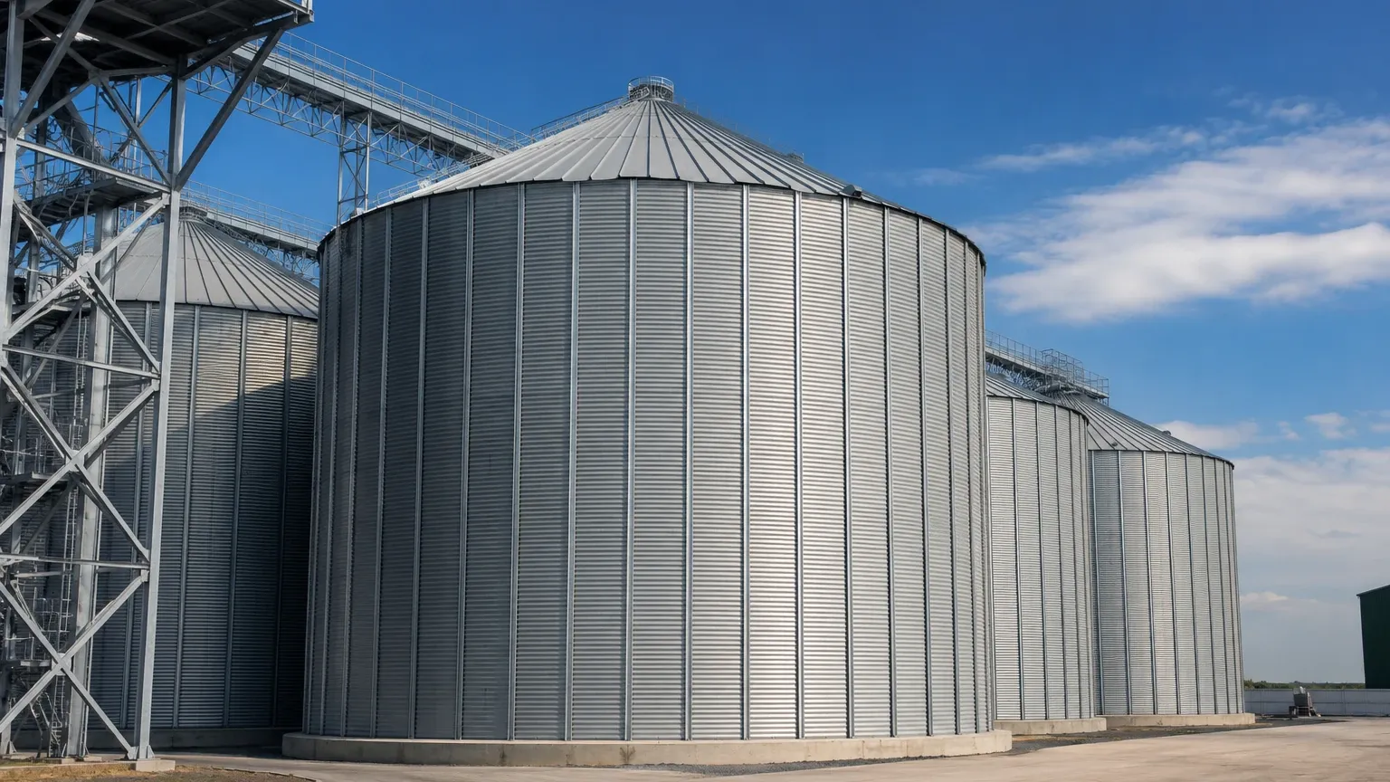
Silo level monitoring is a critical component of bulk solids management in industries ranging from agriculture and food processing to cement production and chemical manufacturing. Unlike liquid level measurement, monitoring solids in silos presents unique challenges, including dust, uneven material surfaces, and varying dielectric constants. Accurate inventory management ensures production continuity, prevents hazardous overfills, and optimizes logistics.
Selecting the appropriate technology for silo level monitoring requires a deep understanding of the material properties and the physical environment within the vessel. This guide explores the principles of measurement, selection criteria, and practical installation strategies for industrial applications.
Measurement Principles for Silo Level Monitoring
Level measurement in silos is generally categorized into continuous measurement and point level detection. Continuous measurement provides real-time data on the volume or height of the material, while point level detection identifies when the material reaches a specific threshold (high or low).
Non-Contact Radar (FMCW)
Non-contact radar transmitters, particularly those operating at high frequencies (e.g., 80 GHz), are the preferred choice for many silo applications. These devices emit microwave pulses or a continuous wave (Frequency Modulated Continuous Wave – FMCW) toward the material surface. The time taken for the signal to reflect back to the sensor is used to calculate the distance.
Radar is highly effective in silos because microwaves are largely unaffected by dust, air temperature, or pressure changes. High-frequency radar offers a narrow beam angle, which is essential for avoiding internal obstructions like ladders or agitators in narrow silos.
Ultrasonic Level Sensors
Ultrasonic sensors use sound waves to measure distance. A transducer emits an ultrasonic pulse that reflects off the material surface. The sensor calculates the distance based on the time-of-flight of the sound wave. While cost-effective, ultrasonic technology is sensitive to dust, as particles in the air can scatter the sound waves, leading to signal loss. They are best suited for non-dusty environments or short-range monitoring.
Guided Wave Radar (GWR)
Guided Wave Radar uses a probe (cable or rod) that extends to the bottom of the silo. Low-power microwave pulses are sent along the probe. When the pulse hits the material, the change in the dielectric constant causes a reflection. GWR is highly reliable for materials with low dielectric constants and is unaffected by dust or heavy steam. However, the probe is subject to mechanical stress from the downward pull of the material during discharge.
Laser Level Measurement
Laser sensors emit a narrow light beam to measure the distance to the material surface. Because the beam is extremely focused, lasers can be used in very narrow silos or through small openings. However, like ultrasonic sensors, lasers struggle in heavy dust environments where the beam can be obstructed.
Point Level Switches
For high and low-level alarms, mechanical or electronic switches are used:
* Rotary Paddle Switches: A motor rotates a paddle; when material covers the paddle, the rotation stops, triggering a signal.
* Vibrating Level Switches (Tuning Forks): A fork vibrates at its resonant frequency. When covered by solids, the vibration is dampened, triggering the switch.
* Capacitance Probes: These detect changes in electrical capacitance between the probe and the silo wall as material fills the space.
Technology Selection Guide
Choosing the right instrument for silo level monitoring depends on the material type, silo geometry, and environmental conditions. The following table provides a general recommendation for common bulk solids.
| Material Type | Recommended Technology | Primary Reason |
| :— | :— | :— |
| Grain / Corn | 80 GHz Non-contact Radar | Penetrates dust; handles large volumes. |
| Cement / Fly Ash | 80 GHz Radar or GWR | High dust resistance is mandatory. |
| Plastic Pellets | Ultrasonic or Radar | Low dust; consistent material surface. |
| Fine Powders | Guided Wave Radar | Reliable in extreme dust and low dielectric. |
| Aggregates / Sand | Heavy-duty Radar | Handles abrasive materials and uneven surfaces. |
| Chemical Flakes | Laser or Radar | Precision in narrow vessels. |
For a comprehensive look at available instrumentation and technical specifications, engineers can Review product options and application support on our Main Page.
Installation Considerations
Proper installation is as important as technology selection. Inaccurate readings in silo level monitoring are often caused by poor mounting choices rather than sensor failure.
Mounting Position
Bulk solids do not form a flat surface. During filling, a "cone-up" profile forms, and during discharge, a "cone-down" (funnel) profile occurs. To obtain a representative average level, sensors should typically be mounted at 1/6th to 1/3rd of the silo diameter from the outer wall. Mounting the sensor directly over the discharge outlet or the filling stream should be avoided, as this leads to erratic readings and potential sensor damage.
Beam Angle and Obstructions
Every non-contact sensor has a beam angle. The "footprint" of the signal expands as it travels downward. It is vital to ensure that the signal path is clear of internal silo structures such as reinforcement beams, ladders, or temperature cables. If an obstruction is unavoidable, many modern radar units offer "false echo suppression" software to ignore reflections from fixed objects.
Nozzle Design
The mounting nozzle should be as short as possible. If a nozzle is too long or narrow, the sensor may detect the edge of the nozzle as the material surface (the "near-zone" effect). For radar sensors, the antenna should ideally extend slightly beyond the bottom of the nozzle.
Aiming Flanges
Because of the angle of repose (the steepest angle at which a material remains stable), the material surface is often slanted. Using an adjustable aiming flange allows the technician to tilt the sensor so the beam is perpendicular to the material slope, maximizing the reflected signal strength back to the transducer.
Limitations and Challenges
Despite advancements in technology, silo level monitoring remains complex due to several physical factors:
1. Dust and Vapor: Heavy dust during pneumatic filling can attenuate signals. While 80 GHz radar performs well, extreme conditions may still require air purging systems to keep the sensor face clean.
2. Low Dielectric Materials: Some materials, like expanded polystyrene or certain dry powders, have very low dielectric constants (εr < 1.5). These materials reflect very little microwave energy, making them difficult for standard radar to detect. Guided Wave Radar is often a better fit here.
3. Mechanical Stress: In tall silos, the friction of falling solids can exert several tons of downward force on GWR cables. If the silo is taller than 20 meters (approx. 65 feet), the tensile strength of the cable and the mounting roof must be verified.
4. Rat-holing and Bridging: Sensors measure the distance to the surface directly beneath them. If the material clings to the walls (bridging) or empties only in the center (rat-holing), a single-point sensor may report a full silo even when the outlet is empty. In these cases, multiple sensors or acoustic 3D scanners may be required.
Integration and Data Management
Modern silo level monitoring systems are rarely standalone. They typically output a 4-20mA signal with HART protocol, or digital signals via Modbus RS485 or Profibus. This allows the level data to be integrated into a PLC (Programmable Logic Controller) or a cloud-based inventory management system. Remote monitoring allows facilities to track stock levels across multiple sites, improving supply chain efficiency and reducing the need for manual inspections.
Frequently Asked Questions (FAQ)
Q: Can I use ultrasonic sensors for cement silo level monitoring?
A: It is generally not recommended. The intense dust generated during the pneumatic filling of cement silos absorbs ultrasonic sound waves, leading to frequent signal loss. Radar is a much more reliable choice for cement.
Q: How does the angle of repose affect my measurement?
A: The angle of repose creates a cone shape. If you measure at the peak, you overestimate volume; if you measure at the wall, you underestimate it. Mounting the sensor at the 1/6th diameter position provides a measurement that most closely represents the average volume.
Q: Do radar sensors require frequent calibration?
A: No. Radar sensors are solid-state and do not have moving parts. Once calibrated to the silo's dimensions (Empty and Full distances), they typically do not drift. Periodic inspection of the antenna face for material buildup is recommended.
Q: What is the maximum height a radar sensor can measure in a silo?
A: Modern high-frequency radar units can measure distances up to 120 meters (approx. 393 feet), making them suitable for the largest industrial grain terminals and cement storage domes.
Q: How do I handle signal interference from internal ladders?
A: Use a sensor with a narrow beam angle (e.g., 3 degrees) and utilize the "False Echo Mapping" feature found in the instrument's software to program the sensor to ignore reflections from known static objects.
By understanding these principles and selecting the right technology, industrial operators can ensure that their silo level monitoring systems provide the accuracy and reliability needed for modern process automation.