Smart Pressure Transmitter
Smart Pressure Transmitter
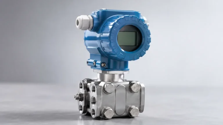
In the landscape of modern industrial automation, the smart pressure transmitter has emerged as a cornerstone for precise process control and monitoring. Unlike traditional analog transmitters that merely convert physical pressure into a basic electrical signal, smart pressure transmitters incorporate microprocessors that enable bi-directional communication, advanced diagnostics, and high-level signal processing. This article provides a comprehensive engineering reference for understanding, selecting, and implementing smart pressure transmitters in various industrial environments, with a particular focus on their role in level measurement.
Understanding the Fundamentals of Smart Pressure Transmitters
A smart pressure transmitter is an integrated device designed to measure the pressure of gases, liquids, or steam and transmit the data to a control system, such as a PLC (Programmable Logic Controller) or DCS (Distributed Control System). The "smart" designation refers to the inclusion of an onboard microprocessor. This internal intelligence allows the device to perform complex mathematical functions, compensate for environmental variables, and communicate via digital protocols like HART (Highway Addressable Remote Transducer), FOUNDATION Fieldbus, or PROFIBUS.
For engineers and plant managers seeking reliable instrumentation, it is essential to recognize that these devices do more than report a single variable. They provide a wealth of secondary data, including sensor temperature, device health status, and historical peak values. When evaluating instrumentation for a facility, visiting the Main Page of a specialized manufacturer can provide deeper insights into the specific hardware configurations available for distinct industrial sectors.
Measurement Principles: From Pressure to Process Data
The operation of a smart pressure transmitter begins with a sensing element, typically a piezoresistive, capacitive, or resonant silicon sensor. Each type has specific characteristics suited for different pressure ranges and environmental conditions.
Hydrostatic Level Measurement
In many industrial applications, pressure transmitters are utilized to determine the level of a liquid in a tank. This is based on the hydrostatic principle, where the pressure ($P$) at the bottom of a liquid column is directly proportional to the height ($h$) of the liquid, its density ($
ho$), and the force of gravity ($g$):
$$P = \rho \cdot g \cdot h$$
By measuring the pressure exerted by the liquid column, the smart pressure transmitter can calculate the level with high accuracy. In an open tank, a gauge pressure transmitter is used, referencing atmospheric pressure. In a closed, pressurized vessel, a differential pressure (DP) transmitter is required to subtract the internal head pressure from the total pressure measured at the bottom.
Signal Processing and Compensation
The microprocessor within the smart pressure transmitter plays a critical role in refining the raw sensor data. Sensors are inherently non-linear and sensitive to temperature fluctuations. The microprocessor applies factory-calibrated characterization curves to the raw signal to correct for these errors in real-time. This results in a significantly higher Total Probable Error (TPE) performance compared to older analog models.
Key Features and Technological Advantages
The transition from legacy analog systems to smart pressure transmitter technology offers several distinct advantages that impact both operational efficiency and maintenance costs.
1. High Rangeability (Turndown Ratio): Smart transmitters allow for a wide range of adjustment. A single device might be capable of measuring from 0–10 kPa (0–1.45 psi) up to 0–100 kPa (0–14.5 psi) without a loss in precision. This reduces the inventory of spare parts required on-site.
2. Digital Communication: By using the HART protocol, digital data is superimposed on the standard 4-20mA analog loop. This allows technicians to configure, calibrate, and troubleshoot the device remotely using a handheld communicator or a PC-based asset management system.
3. Self-Diagnostics: These devices constantly monitor their own health. If a sensor failure, electronic malfunction, or process over-pressure occurs, the transmitter can send a specific error code, allowing for proactive maintenance rather than reactive repairs.
4. Local Display and Interface: Most smart transmitters feature an integrated LCD that displays the pressure, percentage of range, and diagnostic messages, providing immediate feedback to field personnel.
Selection Criteria for Industrial Applications
Choosing the correct smart pressure transmitter requires a detailed analysis of the process conditions and the physical properties of the medium being measured. The following table provides a general guide for selection based on common industrial scenarios.
| Application | Recommended Transmitter Type | Sensing Element | Typical Accuracy | Key Consideration |
| :— | :— | :— | :— | :— |
| Clean Water Storage | Gauge Pressure | Piezoresistive | ±0.075% | Atmospheric venting |
| Pressurized Chemical Tank | Differential Pressure | Capacitive | ±0.04% | Static pressure limits |
| High-Viscosity Slurries | Diaphragm Seal System | Metallic Diaphragm | ±0.1% | Capillary length and temp |
| Steam Flow/Level | Differential Pressure | Resonant Silicon | ±0.05% | Condensate pot requirement |
| Vacuum Distillation | Absolute Pressure | Ceramic/Silicon | ±0.1% | Full vacuum protection |
Material Compatibility
The wetted parts of the transmitter, including the diaphragm and process connections, must be compatible with the process fluid. While 316L Stainless Steel is standard, aggressive chemicals may require exotic materials such as Hastelloy C, Monel, Tantalum, or Gold plating to prevent corrosion and hydrogen permeation.
Installation and Commissioning Best Practices
Proper installation is paramount to ensuring the longevity and accuracy of a smart pressure transmitter. Even the most advanced device will provide inaccurate data if installed incorrectly.
Mounting and Orientation
Transmitters should be mounted in locations that are easily accessible for maintenance but protected from excessive vibration and extreme temperature swings. For liquid measurements, the transmitter should ideally be mounted below the process tap to ensure the impulse lines remain filled with liquid, preventing air pockets that cause signal drift. For gas measurements, the transmitter should be mounted above the tap to allow condensate to drain back into the process.
Impulse Lines and Manifolds
Impulse lines connect the process to the transmitter. They should be as short as possible and sloped at least 1:12 to allow for proper venting or draining. The use of a three-valve or five-valve manifold is highly recommended. These manifolds allow the transmitter to be isolated from the process and equalized for zero-point calibration without shutting down the entire system.
Electrical Considerations
Smart transmitters are typically loop-powered (two-wire). Ensure that the power supply provides sufficient voltage, accounting for the voltage drop across the load resistor (usually 250 ohms for HART communication) and the resistance of the field wiring. Shielded twisted-pair cable should be used to minimize electromagnetic interference (EMI).

Limitations and Operational Risks
While smart pressure transmitters are highly robust, they are not immune to failure or measurement errors under certain conditions.
* Temperature Effects: Although smart transmitters compensate for temperature, extreme heat can still cause the fill fluid inside the sensor module to expand, leading to a "zero shift." In high-temperature applications (above 120°C / 248°F), remote diaphragm seals or cooling siphons are necessary.
* Clogging and Sedimentary Build-up: In applications involving slurries or fluids that crystallize, the small process ports of a standard transmitter can become blocked. Flush-mounted diaphragms are the preferred solution for these environments.
* Hydrogen Permeation: In high-pressure hydrogen service, hydrogen atoms can diffuse through standard metal diaphragms, causing internal pressure build-up and sensor failure. Gold-plated diaphragms are often required to mitigate this risk.
* Over-pressure Events: Every transmitter has a Maximum Working Pressure (MWP). Exceeding this limit can permanently deform the sensing diaphragm, leading to inaccurate readings or total failure.
Maintenance and Calibration
One of the primary benefits of smart technology is the extension of calibration intervals. Unlike analog transmitters that might require quarterly calibration, a high-quality smart pressure transmitter may only need verification every two to five years, depending on the criticality of the process.
Calibration involves a "Zero Trim" and a "Sensor Trim." The Zero Trim corrects for mounting position effects, while the Sensor Trim aligns the transmitter's digital reading with a known pressure standard. It is important to distinguish between "Reranging" (changing the 4mA and 20mA points via software) and "Calibration" (adjusting the actual sensor response).
Frequently Asked Questions (FAQs)
Q: Can a smart pressure transmitter be used for both level and flow measurement?
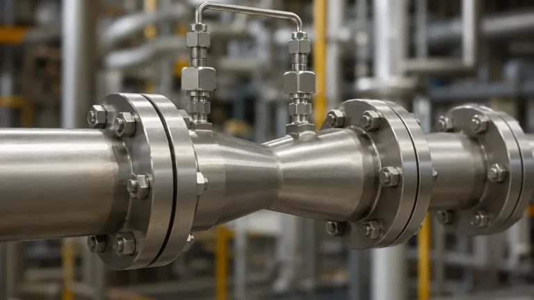
A: Yes. When used with a primary flow element like an orifice plate, a differential pressure smart transmitter can calculate flow rate based on the square root of the pressure drop. Most smart transmitters have a selectable "square root extraction" function for this purpose.
Q: What is the difference between HART 5, 6, and 7?
A: These are different versions of the HART communication protocol. Higher versions offer more data points and improved wireless capabilities. Most modern smart transmitters are compatible with HART 7 but can fall back to HART 5 for compatibility with older host systems.
Q: How does a diaphragm seal affect the response time of the transmitter?
A: A diaphragm seal system uses a capillary tube filled with oil to transmit pressure. This can introduce a slight delay in response time, especially with long capillaries or high-viscosity fill fluids. This must be accounted for in fast-acting control loops.
Q: Is it necessary to ground the transmitter housing?
A: Yes, for safety and to reduce noise. The transmitter housing should be grounded to the plant's earth system, while the signal wire shield should typically be grounded at only one end (usually at the control system) to prevent ground loops.
Conclusion
The smart pressure transmitter represents a significant leap forward in process instrumentation. By integrating advanced sensing technology with powerful microprocessors and digital communication, these devices provide the accuracy, reliability, and diagnostic depth required for modern industrial operations. Whether used for simple pressure monitoring or complex hydrostatic level calculations, understanding the technical nuances of these instruments is essential for optimizing process performance. For further technical specifications and product selection, engineers are encouraged to consult the Main Page of reputable manufacturers to ensure the chosen solution meets the specific demands of their application.