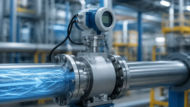
Ultrasonic Flow Switch
Ultrasonic Flow Switch
In modern industrial automation, the ability to monitor fluid movement without interrupting the process flow is a critical requirement for efficiency and safety. An ultrasonic flow switch serves as a non-invasive monitoring device designed to detect the presence or absence of flow within a pipe, or to trigger an alarm when the flow rate crosses a specific threshold. Unlike traditional mechanical switches that rely on paddles or moving parts, ultrasonic technology utilizes sound waves to determine flow velocity, offering a high degree of reliability and reduced maintenance requirements.
As industries move toward smarter, more connected systems, the ultrasonic flow switch has become a preferred choice for applications ranging from pump protection in water treatment plants to chemical dosing monitoring in pharmaceutical manufacturing. This guide provides a technical overview of how these devices operate, their selection criteria, and the practical considerations necessary for successful implementation.
Understanding Ultrasonic Flow Switch Technology
An ultrasonic flow switch operates on the principle of acoustic wave propagation through a liquid medium. The device typically consists of one or more pairs of transducers that act as both transmitters and receivers of high-frequency sound waves. Because these transducers are often clamped to the outside of the pipe or mounted in a way that does not obstruct the flow path, they are classified as non-intrusive or minimally intrusive instruments.
The primary function of the switch is to provide a discrete output—such as a relay contact or a digital signal—when flow conditions meet a pre-programmed set point. This differentiates it from an ultrasonic flow meter, which provides a continuous measurement of flow volume. However, many modern switches are built upon the same core technology as meters, providing high precision in detecting low-flow or no-flow conditions.
Measurement Principles: Transit-Time vs. Doppler
To select the correct ultrasonic flow switch, engineers must first understand the two primary measurement techniques: Transit-Time and Doppler Effect. The choice between these two depends entirely on the characteristics of the fluid being monitored.
1. Transit-Time Principle
Transit-time ultrasonic flow switches work by measuring the time difference between an ultrasonic pulse sent in the direction of the flow and one sent against it.
* Mechanism: When the fluid is moving, the pulse traveling with the flow reaches the receiving transducer faster than the pulse traveling against the flow. The time difference (delta-T) is directly proportional to the flow velocity.
* Fluid Requirements: This method requires "clean" liquids with very low concentrations of suspended solids or entrained air bubbles (typically less than 2% by volume). If the liquid is too dirty, the sound waves are scattered or absorbed, leading to signal loss.
* Common Applications: Potable water, deionized water, cooling oils, and clear chemicals.
2. Doppler Effect Principle
Doppler ultrasonic flow switches rely on the frequency shift of a sound wave reflected off moving particles or bubbles within the liquid.
* Mechanism: The transducer transmits a continuous high-frequency sound into the pipe. If the fluid contains reflectors (solid particles or air bubbles) moving at the same velocity as the liquid, the reflected sound will have a different frequency. The switch calculates the flow velocity based on this frequency shift.
* Fluid Requirements: This method requires a minimum concentration of suspended solids or bubbles (usually at least 100 parts per million, with a size of 75 microns or larger) to provide enough reflection for an accurate reading.
* Common Applications: Wastewater, slurries, aerated liquids, and raw sewage.
Key Advantages in Industrial Applications
Choosing an ultrasonic flow switch over mechanical alternatives like paddle-wheel or thermal dispersion switches offers several distinct advantages:
* Zero Pressure Drop: Since non-invasive (clamp-on) ultrasonic switches do not protrude into the pipe, they do not cause any restriction or pressure loss. This is particularly valuable in gravity-fed systems or high-volume pumping applications where energy efficiency is a priority.
* No Moving Parts: Mechanical switches are subject to wear, corrosion, and clogging. Ultrasonic sensors have no internal moving components, significantly extending the service life and reducing the total cost of ownership.
* Chemical Compatibility: Because clamp-on sensors never touch the process medium, they are immune to corrosive acids, caustic bases, and abrasive slurries. This eliminates the need for expensive exotic alloys in the sensor construction.
* Ease of Retrofitting: Clamp-on ultrasonic flow switches can be installed on existing piping without shutting down the process or cutting the pipe. This reduces installation labor and prevents costly downtime.
Selection Criteria and Technical Specifications
When evaluating an ultrasonic flow switch for a specific project, several technical parameters must be confirmed to ensure reliable performance. For a broader look at how these instruments integrate into wider process control systems, you may review product options and application support on our Main Page.
Practical Selection Table
| Feature | Transit-Time Switch | Doppler Switch |
| :— | :— | :— |
| Best Fluid Type | Clean, clear liquids | Slurries, aerated liquids |
| Solid Concentration | < 2% by volume | > 100 ppm (typically) |
| Pipe Materials | Most metals and plastics | Most metals and plastics |
| Installation Style | Clamp-on or Spool-piece | Clamp-on or Spool-piece |
| Accuracy Range | 1% to 3% of velocity | 2% to 5% of velocity |
| Maintenance | Very Low | Very Low |
Critical Evaluation Factors
1. Pipe Material and Lining: Ultrasonic waves must pass through the pipe wall. While most metals (carbon steel, stainless steel, ductile iron) and plastics (PVC, PE, PVDF) are excellent conductors, pipes with internal liners (like cement or loose plastic liners) can present challenges. If a liner is present, it must be well-bonded to the pipe wall to prevent air gaps that block the signal.
2. Fluid Temperature: Standard ultrasonic transducers typically handle temperatures up to 80°C (176°F). For high-temperature applications (up to 200°C or higher), specialized high-temperature transducers and mounting hardware are required.
3. Flow Velocity Range: Ensure the switch is sensitive enough to detect the minimum flow rate required for your application. Many ultrasonic switches can detect velocities as low as 0.1 m/s (0.33 ft/s).
4. Output Requirements: Determine if the application requires a simple SPDT relay, a solid-state switch, or a digital communication protocol like Modbus or HART for integration into a PLC (Programmable Logic Controller).
Installation Best Practices for Accuracy
Proper installation is the single most important factor in the performance of an ultrasonic flow switch. Even the most advanced sensor will fail if the acoustic path is compromised.
Pipe Configuration
To ensure a stable and laminar flow profile, the switch should be installed on a straight section of pipe. The industry standard recommendation is:
* Upstream: At least 10 pipe diameters (10D) of straight pipe after any elbows, valves, or pumps.
* Downstream: At least 5 pipe diameters (5D) of straight pipe before the next fitting.
If the pipe is vertical, the flow should always be in the upward direction. This ensures that the pipe remains completely full of liquid and prevents air pockets from collecting at the sensor location.
Transducer Mounting
For clamp-on installations, the pipe surface must be cleaned of rust, scale, and loose paint. A thin layer of acoustic coupling gel (ultrasonic grease) must be applied between the transducer face and the pipe wall to eliminate any air gaps.
On horizontal pipes, transducers should be mounted at the "3 o'clock" and "9 o'clock" positions. Avoid the top of the pipe (where air bubbles collect) and the bottom of the pipe (where sediment settles), as both conditions will interfere with the ultrasonic signal.
Limitations and Operating Constraints
While highly versatile, ultrasonic flow switches have specific limitations that engineers must account for during the design phase:
* Full Pipe Requirement: The pipe must be completely full of liquid. Ultrasonic waves cannot travel through air or a partially filled pipe, which will result in a "Signal Loss" error or a false no-flow indication.
* Acoustic Short-Circuiting: In some very thick-walled pipes or specific composite materials, the sound wave may travel through the pipe wall faster than through the liquid, leading to inaccurate readings. This is often mitigated by advanced signal processing software.
* High Viscosity: Extremely viscous liquids (like heavy molasses or thick polymers) can attenuate the ultrasonic signal, requiring higher-powered transducers.
* Flow Profile Disturbances: Severe turbulence caused by a partially open valve immediately upstream can disrupt the acoustic path. Always place the switch as far from turbulence sources as possible.
Maintenance and Troubleshooting Guide
One of the primary reasons B2B customers choose ultrasonic technology is the minimal maintenance required. However, periodic checks are recommended to ensure long-term reliability.
Common Issues and Solutions
* Low Signal Strength: This is often caused by the drying out of the coupling gel in clamp-on applications. Re-applying the gel or using a permanent silicone-based couplant can resolve this.
* Erratic Switching: If the switch triggers unexpectedly, check for electrical noise from nearby Variable Frequency Drives (VFDs). Ensure that shielded cables are used and properly grounded.
* False Flow Indication: This can occur if there is significant vibration in the piping system that the sensor interprets as flow. Using vibration-dampening mounts or adjusting the switch's sensitivity (damping) settings can help.
Maintenance Checklist
1. Inspect transducer cables for signs of wear or environmental damage.
2. Verify the integrity of the coupling gel on clamp-on sensors annually.
3. Check the PLC interface to ensure the signal is being received correctly.
4. Clean the pipe surface if any corrosion is visible near the sensor mounting point.
Frequently Asked Questions (FAQs)
Q: Can an ultrasonic flow switch work on metal pipes with thick paint?
A: Yes, but the paint must be well-bonded to the metal. If the paint is flaking or contains air bubbles, it must be sanded down to the bare metal at the point of contact for the transducers.
Q: Is there a minimum pipe size for ultrasonic flow switches?
A: Most industrial ultrasonic switches are designed for pipes 15 mm (1/2 inch) and larger. For very small tubing, specialized inline sensors are usually more effective than clamp-on models.
Q: How does the switch handle different liquid densities?
A: Since ultrasonic switches measure velocity, changes in density (due to temperature or concentration) have a negligible effect on the switching point compared to mass flow meters.
Q: Can I use a transit-time switch for wastewater?
A: Generally, no. Wastewater typically contains too many solids and bubbles, which will block the transit-time signal. A Doppler-style switch is the correct choice for wastewater applications.
Conclusion
The ultrasonic flow switch represents a significant advancement in industrial process monitoring, providing a non-contact, maintenance-free solution for flow detection. By understanding the differences between Transit-Time and Doppler principles and adhering to strict installation guidelines regarding pipe straightness and transducer coupling, engineers can ensure high-precision monitoring in even the most demanding environments.
Whether protecting a high-value pump from dry-running or ensuring the consistent delivery of cooling water to a reactor, the reliability of ultrasonic technology makes it a cornerstone of modern industrial safety. For further technical specifications or to discuss custom OEM/ODM solutions for your specific application, please refer to the resources available on our Main Page.