Static Water Level in a Well
Static Water Level in a Well
In industrial water management, municipal supply, and agricultural irrigation, understanding the behavior of an aquifer is fundamental to operational efficiency. One of the most critical metrics in this field is the static water level in a well. This measurement serves as the baseline for assessing well yield, pump health, and the overall sustainability of the water source.
For engineers and site managers, monitoring the static water level is not a one-time task but a continuous requirement. Accurate data ensures that pumps are not oversized, energy is not wasted, and the well is not over-pumped to the point of structural damage or saline intrusion. This article explores the technical principles of measuring the static water level, the technologies available, and the practical considerations for sensor selection and installation.
Defining Static Water Level
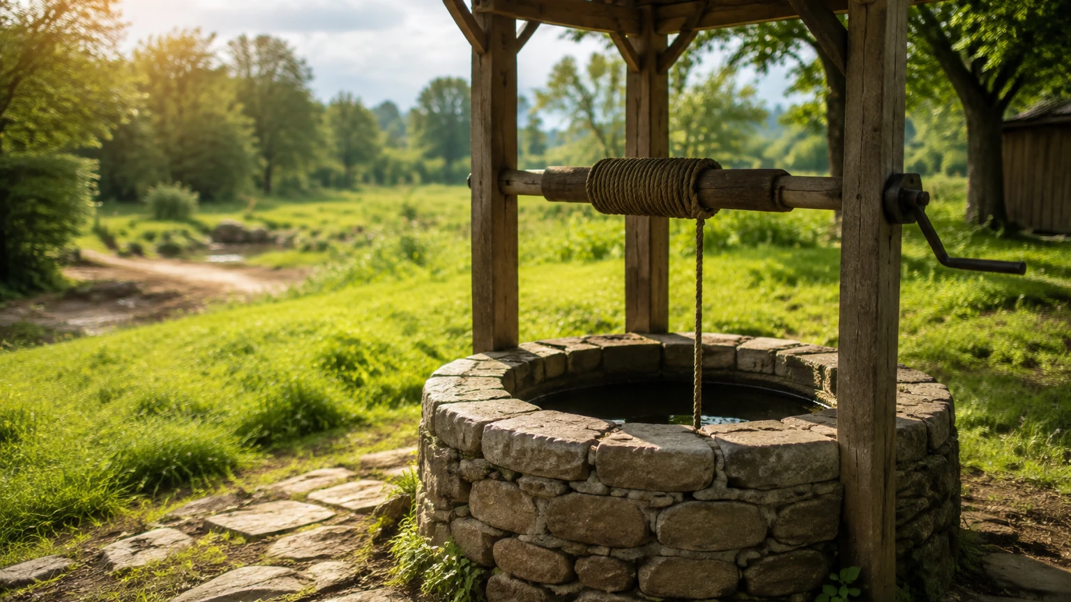
The static water level (SWL) is the distance from the ground surface (or a specific reference datum like the top of the well casing) to the water surface when the well is at rest. "At rest" implies that no pumping has occurred for a sufficient duration to allow the water level to stabilize and reach equilibrium with the surrounding aquifer pressure.
It is distinct from the dynamic water level (DWL), which is the level reached during active pumping. The difference between the static and dynamic levels is known as the "drawdown." Monitoring the static water level in a well over long periods allows operators to track seasonal fluctuations and long-term aquifer depletion.
Measurement Principles and Technologies
Choosing the right instrument depends on the depth of the well, the required accuracy, and whether the data needs to be logged or transmitted to a control system. As a professional manufacturer, Welk provides various technologies to meet these diverse needs.
1. Hydrostatic Pressure Measurement
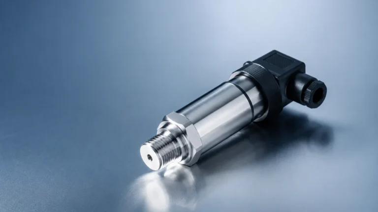
Hydrostatic level transmitters are the most common solution for continuous monitoring of the static water level in a well. These sensors are submerged below the water surface.
Principle: The sensor measures the pressure exerted by the column of liquid above it. According to the hydrostatic law:
*P = ρ × g × h*
Where *P* is pressure, *ρ* is the density of the liquid, *g* is gravity, and *h* is the height of the liquid column.
To ensure accuracy, these sensors must compensate for atmospheric pressure changes. This is typically achieved using a vented cable that allows the internal side of the sensor diaphragm to remain at atmospheric pressure. This ensures that the sensor only measures the pressure of the water column itself.
2. Ultrasonic (Non-Contact) Measurement
Ultrasonic sensors are mounted at the top of the well casing. They emit high-frequency sound pulses that reflect off the water surface.
Principle: The sensor measures the time it takes for the pulse to travel to the surface and back. Since the speed of sound in air is known (approximately 343 m/s at 20°C), the distance can be calculated.
While cost-effective and easy to install, ultrasonic sensors can be affected by temperature gradients within the well, narrow well casings that cause signal interference, and the presence of foam or turbulence on the water surface.
3. Radar Level Measurement
Radar technology, particularly 80GHz high-frequency radar, has become increasingly popular for deep wells or wells with narrow diameters.
Principle: Similar to ultrasonic, radar uses electromagnetic waves. These waves travel at the speed of light and are unaffected by air temperature, pressure, or vapor. Radar provides higher precision (often within ±2mm) and can penetrate narrow openings without the signal "spreading" and hitting the well walls.
4. Manual Electric Contact Meters
Often referred to as "dip meters" or "water level tapes," these are used for periodic manual verification. A probe is lowered into the well; when it touches the water surface, a circuit is completed, triggering a light or buzzer. The operator then reads the depth from the graduated tape.
Selection Criteria for Well Monitoring
When selecting a system to monitor the static water level in a well, engineers should evaluate the following criteria:
| Feature | Hydrostatic Transmitter | Ultrasonic Sensor | Radar Level Meter |
| :— | :— | :— | :— |
| Measurement Range | Up to 500m+ | Typically up to 15m | Up to 120m |
| Accuracy | 0.1% to 0.5% FS | 0.25% to 0.5% FS | ±2mm to ±5mm |
| Installation | Submerged (Requires cable) | Top-mounted | Top-mounted |
| Maintenance | Low (Check for clogging) | Moderate (Clean sensor face) | Very Low |
| Cost | Mid-range | Low to Mid-range | Higher |
| Best For | Deep wells, constant logging | Shallow wells, open basins | Narrow casings, high precision |
For professionals seeking specific hardware configurations, visiting the Main Page of a dedicated manufacturer like Welk provides access to technical datasheets and selection tools tailored for industrial automation.
Installation Considerations and Best Practices
Correct installation is paramount to obtaining reliable data regarding the static water level in a well. Improperly installed sensors can lead to data drift or mechanical failure.
Vented Cable Management
For hydrostatic sensors, the vented tube inside the cable must remain unobstructed. If moisture enters the vent tube, it can block the atmospheric reference, leading to significant measurement errors. It is recommended to use a desiccant cartridge at the termination point of the cable to prevent condensation.
Stilling Wells
In wells where there is significant turbulence or where the pump is located close to the sensor, a stilling well (a perforated pipe) should be installed. This pipe protects the sensor from lateral water movement and ensures a stable surface for non-contact sensors like radar or ultrasonic.
Sensor Placement
The sensor should be placed deep enough to remain submerged even during maximum drawdown (dynamic level) but should not be placed at the very bottom of the well. Placing the sensor too low risks it being buried by silt or sediment, which can clog the pressure port of a hydrostatic transmitter.
Lightning and Surge Protection
Because well sensors are often connected to long cables in outdoor environments, they are susceptible to lightning strikes and electrical surges. Using sensors with built-in surge protection and installing external lightning arrestors at the control panel is a standard industrial best practice.
Limitations and Environmental Factors
Several factors can influence the accuracy of the static water level in a well measurement:
1. Water Density: Hydrostatic sensors assume a constant water density. If the well water has high salinity (brackish water) or high mineral content, the density will be higher than pure water, requiring a calibration adjustment.
2. Atmospheric Pressure: Without proper venting or a secondary barometric sensor for compensation, changes in weather can cause the perceived water level to shift by several centimeters.
3. Well Verticality: If a well is not perfectly vertical, manual tape measurements or long cable runs for hydrostatic sensors may reflect a greater depth than the true vertical distance.
4. Temperature: For ultrasonic sensors, the speed of sound changes with air temperature. In deep wells where the air temperature near the water surface differs from the surface temperature, integrated temperature compensation is required.
Data Interpretation: Static vs. Dynamic
Understanding the static water level in a well is only the first step. By comparing the SWL with the dynamic water level, operators can calculate the Specific Capacity of the well.
*Specific Capacity = Discharge Rate (Q) / Drawdown (s)*
A decrease in specific capacity over time often indicates a problem, such as well screen clogging (encrustation) or a decline in the aquifer's ability to yield water. Regular monitoring of the static level during pump-off periods is the only way to distinguish between a failing pump and a failing well.
Frequently Asked Questions (FAQ)
Q: How long should I wait to measure the static water level after the pump stops?
A: This depends on the aquifer's recovery rate. In highly permeable gravel aquifers, recovery may take minutes. In tight clay or silt formations, it may take 24 hours or more. Continuous monitoring with a data logger is the best way to determine when the level has truly stabilized.
Q: Can I use a standard pressure transmitter for well levels?
A: Standard transmitters are usually not designed for submersion. You must use a purpose-built submersible level transmitter with a high IP rating (IP68) and a reinforced, vented cable.
Q: How often should I calibrate my level sensor?
A: For industrial applications, a manual check using an electric contact meter should be performed every 6 to 12 months to verify the accuracy of the electronic sensor and adjust for any drift.
Q: What is the impact of a narrow well casing on radar sensors?
A: Traditional radar sensors had wide beam angles that would reflect off the casing walls. However, modern 80GHz radar sensors have very narrow beam angles (as small as 3 degrees), making them ideal for measuring the static water level in a well even through narrow pipes.
Conclusion
Accurate measurement of the static water level in a well is the cornerstone of sustainable groundwater management. Whether utilizing the robust simplicity of hydrostatic transmitters or the high-precision capabilities of 80GHz radar, selecting the right technology requires a clear understanding of the well's physical characteristics and the operational goals of the facility. By following rigorous installation standards and accounting for environmental variables, engineers can ensure long-term reliability and protect the integrity of their water supply infrastructure.