Systematic Failure
Systematic Failure
In the field of industrial automation and process control, the reliability of level measurement instruments is paramount. Engineers often distinguish between two primary types of failures: random hardware failures and systematic failure. While random failures are typically the result of physical degradation or wear and tear over time, a systematic failure is inherently tied to a flaw in the design, manufacturing, installation, or operation of the system. Understanding and mitigating systematic failure is essential for maintaining functional safety and operational efficiency in demanding environments like chemical processing, water treatment, and oil and gas storage.
This guide explores the nature of systematic failure within level measurement applications, provides a technical overview of common measurement principles, and offers practical strategies for selecting and installing instruments to minimize systematic risks.
Understanding Systematic Failure in Level Measurement
According to international standards such as IEC 61508 and IEC 61511, a systematic failure is a failure related in a deterministic way to a certain cause, which can only be eliminated by a modification of the design or the manufacturing process, operational procedures, documentation, or other relevant factors.
Unlike random failures, which can be predicted using statistical methods (such as Mean Time Between Failures or MTBF), systematic failures are "built-in." If the same conditions occur again, the failure will repeat with 100% certainty. Common examples include:
* Software Errors: Bugs in the signal processing algorithms of a radar level meter.
* Design Flaws: An ultrasonic sensor that cannot handle the specific frequency of ambient noise in a factory.
* Specification Errors: Choosing a hydrostatic transmitter for a tank where the fluid density varies significantly without compensation.
* Installation Errors: Mounting a level switch in a "dead zone" where turbulence prevents accurate detection.
To ensure high reliability, manufacturers like Welk focus on "Systematic Capability," a measure of the confidence that the systematic safety integrity of an element is sufficient to meet the requirements of a specified Safety Integrity Level (SIL).
Core Level Measurement Principles
Before addressing failure mitigation, it is vital to understand the physics behind common level measurement technologies. Each principle has specific strengths and inherent vulnerabilities to systematic issues.
1. Radar Level Measurement (ToF)
Radar level meters operate on the Time-of-Flight (ToF) principle. They emit high-frequency electromagnetic waves (typically in the 26 GHz or 80 GHz range). These waves travel at the speed of light, reflect off the surface of the medium, and return to the sensor. The distance is calculated based on the time delay. Because radar waves do not require a medium for propagation, they are largely unaffected by vacuum, pressure, or temperature changes.
2. Ultrasonic Level Sensors
Ultrasonic sensors also use the ToF principle but employ sound waves instead of electromagnetic waves. A transducer emits an ultrasonic pulse (usually between 20 kHz and 200 kHz), which reflects off the product surface. The speed of sound is highly dependent on the air temperature and composition, making temperature compensation critical for these devices.
3. Hydrostatic Level Transmitters
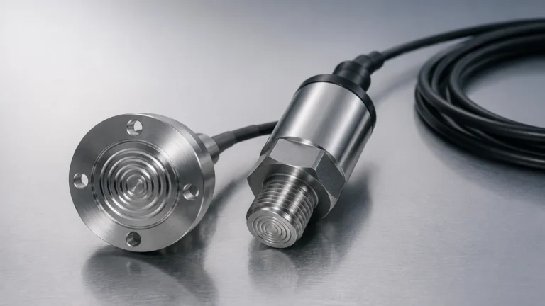
These sensors measure the pressure exerted by a liquid column. Based on the formula $P = \rho \cdot g \cdot h$ (where $P$ is pressure, $\rho$ is density, $g$ is gravity, and $h$ is height), the level can be derived if the density of the liquid is known and constant. This is a contact-based measurement method often used in open tanks or deep wells.
4. Magnetic Level Gauges
Magnetic gauges utilize a float containing a permanent magnet that moves with the liquid level inside a bypass chamber. This magnet actuates a series of external flags or a transmitter. It provides a highly visible local indication without requiring a power source for the primary mechanical display.
Identifying Common Causes of Systematic Failure
In practical engineering, systematic failures often arise during the interface between the instrument and the process. Identifying these risks early is the first step toward a robust system.
Environmental and Process Factors
* Foam and Turbulence: Ultrasonic sensors may experience systematic failure in the presence of heavy foam, as the sound waves are absorbed rather than reflected. Similarly, extreme turbulence can scatter the signal of a low-frequency radar.
* Vapor and Gas Layers: While radar is robust, certain high-pressure vapors can slightly alter the propagation speed of the signal, leading to a systematic offset if not accounted for in the device settings.
* Build-up and Coating: For contact-based methods or even some non-contact sensors with antennas, the accumulation of sticky media (e.g., resins or heavy oils) can cause the sensor to "lock" at a high-level reading, a classic systematic failure mode.
Human and Procedure-Related Factors
* Incorrect Calibration: If a hydrostatic transmitter is calibrated for water (density 1,000 kg/m³) but used for an oil with a density of 800 kg/m³, the level reading will systematically underreport the actual height by 20%.
* Inadequate Shielding: Electromagnetic interference (EMI) from nearby variable frequency drives (VFDs) can introduce systematic noise into the 4-20mA signal loop if the cabling is not properly shielded and grounded.
Selection Table for Minimizing Systematic Risk
Choosing the right technology for the specific application is the most effective way to prevent systematic failure. The following table compares technologies based on their susceptibility to common systematic issues.
| Technology | Systematic Strengths | Systematic Risks | Ideal Applications |
| :— | :— | :— | :— |
| 80 GHz Radar | High focus, ignores internal obstructions, unaffected by vapor. | High cost, dielectric constant ($ε_r$) must be > 1.4. | Chemical reactors, storage tanks with agitators. |
| Ultrasonic | Cost-effective, non-contact, easy to install. | Affected by foam, wind, and temperature gradients. | Water/wastewater, open channels, sumps. |
| Hydrostatic | Simple physics, reliable in clean liquids. | Density changes cause errors; diaphragm damage risk. | Deep wells, vented water tanks, fuel storage. |
| Magnetic Gauge | No power needed for local display, high pressure/temp. | Float can get stuck if solids are present; mechanical wear. | Boilers, oil-water separators, high-pressure vessels. |
| Level Switch | Simple point detection, high redundancy. | Mechanical fatigue, coating on the probe/tuning fork. | Overfill protection, dry-run protection for pumps. |

Installation Considerations to Prevent Systematic Errors
Even the best instrument can suffer from systematic failure if installed incorrectly. Engineers should follow these guidelines to ensure long-term accuracy:
1. Nozzle Geometry: For radar and ultrasonic sensors, the nozzle height should be kept to a minimum. If a nozzle is too long and narrow, the sensor may detect the edge of the nozzle as the "liquid level," leading to a false high-level reading.
2. Obstruction Mapping: Modern radar level meters allow for "False Echo Suppression." During commissioning, the engineer should map out internal tank structures (ladders, pipes, agitators) while the tank is empty. Failure to do this is a common source of systematic measurement errors.
3. Stilling Wells: In applications with heavy turbulence or boiling surfaces, installing the sensor inside a stilling well or bypass pipe can provide a calm surface for measurement, eliminating systematic noise issues.
4. Environmental Shielding: For ultrasonic sensors used outdoors, a sunshade should be installed to prevent the sensor body from heating up significantly more than the surrounding air, which would skew the internal temperature compensation.
Limitations and Boundary Conditions
It is important to recognize that no single technology is immune to systematic failure across all conditions. For instance, while radar is often seen as a "universal" solution, it struggles with extremely low dielectric materials (like liquid nitrogen or certain dry powders) unless a guided wave radar (GWR) or a large antenna is used.
Furthermore, systematic capability is often limited by the complexity of the software. In safety-instrumented systems (SIS), it is often preferable to use two different technologies (e.g., a radar level meter and a hydrostatic transmitter) to achieve "diverse redundancy." This ensures that a systematic flaw inherent in one technology (like a density change affecting the hydrostatic sensor) will not affect the other, thereby preventing a common-cause failure.
Frequently Asked Questions (FAQs)
Q: How does SIL rating relate to systematic failure?
A: A SIL (Safety Integrity Level) rating consists of two parts: hardware fault tolerance (for random failures) and systematic capability (SC). An instrument rated SC3, for example, has been designed and manufactured following rigorous processes to minimize the likelihood of systematic failures, making it suitable for use in SIL 3 safety functions.
Q: Can systematic failure be detected during normal operation?
A: Not always. Systematic failures often remain "latent" until a specific set of conditions occurs. This is why regular proof testing—manually simulating a high-level condition or performing a full-range calibration check—is required in high-reliability industries.
Q: Does Welk provide support for custom applications to avoid these failures?
A: Yes. As a professional manufacturer, Welk offers OEM/ODM services to customize sensor frequencies, housing materials, and signal processing logic to match specific industrial challenges, thereby reducing the risk of systematic application errors.
Conclusion
Systematic failure represents a significant challenge in industrial level measurement because it cannot be solved by simply adding more of the same equipment. It requires a deep understanding of the process media, the physics of the measurement technology, and the rigorous application of engineering best practices. By selecting the appropriate technology, performing thorough commissioning, and adhering to strict installation guidelines, operators can significantly reduce the risk of systematic errors.
For engineers looking to specify highly reliable level measurement solutions or to review technical specifications for radar, ultrasonic, and hydrostatic instruments, please visit our Main Page for comprehensive product options and application support. Ensuring the right fit between the instrument and the environment is the most effective defense against systematic failure in any industrial automation project.