Thermal Dispersion Flow Meter
Thermal Dispersion Flow Meter
In the landscape of industrial process control, the thermal dispersion flow meter has established itself as a critical instrument for the precise measurement of gas mass flow. Unlike volumetric flow meters that require additional pressure and temperature compensation to calculate mass, thermal dispersion technology provides a direct mass flow reading. This capability is particularly valuable in applications involving compressed air, aeration air, and various process gases where density fluctuations are common. As industries move toward higher efficiency and stricter environmental monitoring, understanding the nuances of this technology is essential for engineers and facility managers.
Understanding the Measurement Principle
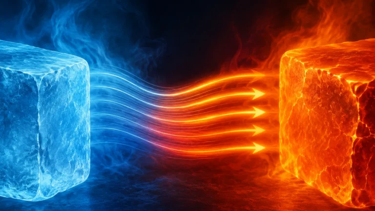
The operation of a thermal dispersion flow meter is rooted in the physical principle of heat transfer. Specifically, it relies on the fact that a fluid (liquid or gas) flowing past a heated surface will carry away heat at a rate proportional to the mass flow of that fluid. This relationship is often described by King’s Law, which relates the heat loss from a wire to the fluid velocity.
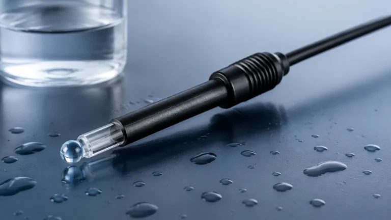
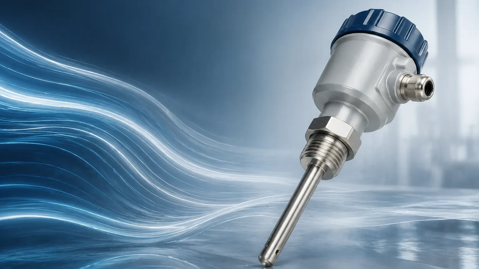
In a practical industrial design, the meter typically employs two high-precision Resistance Temperature Detectors (RTDs) housed within robust metal thermowells.
1. The Reference Sensor: This RTD measures the actual temperature of the process fluid. It provides a baseline for the electronics to understand the ambient conditions of the medium.
2. The Active (Heated) Sensor: This RTD is supplied with a controlled amount of electrical power to maintain it at a specific temperature above the reference sensor.
As the fluid flows past the probe, it absorbs heat from the active sensor. To maintain the predefined temperature differential (often referred to as ΔT), the meter’s electronics must increase the power supplied to the active sensor. Because the cooling effect is directly related to the number of molecules passing the sensor (the mass), the amount of power required to maintain the temperature difference is a direct indicator of the mass flow rate. This allows the instrument to measure flow accurately even if the process pressure or temperature changes, as these factors are inherently accounted for by the heat transfer rate.
Key Components and Design Variations
Thermal dispersion flow meters are generally categorized into two physical configurations: insertion and inline. The choice between these depends largely on pipe size, installation flexibility, and maintenance requirements.
Insertion Flow Meters
Insertion models consist of a probe that is inserted through a nozzle or a thread-o-let into the process piping. They are highly cost-effective for large diameter pipes—typically 50 mm (2 inches) and larger. These units often feature adjustable mounting hardware, such as compression fittings or flanged connections, allowing the sensor to be positioned at the center of the pipe where the flow profile is most stable.
Inline Flow Meters
Inline models feature a dedicated flow body that is installed as a permanent section of the piping. These are preferred for smaller line sizes (usually below 50 mm) where flow profile disturbances are more difficult to manage with an insertion probe. Inline bodies often include built-in flow conditioners to ensure a uniform velocity profile across the sensors, resulting in higher accuracy and repeatability.
Sensor Construction
To withstand harsh industrial environments, the sensors are typically constructed from 316L stainless steel, though exotic alloys like Hastelloy C are used for corrosive gas applications. The electronics are housed in robust enclosures, often with ATEX or IECEx certifications for use in hazardous areas such as oil and gas refineries or chemical plants.
Selection Criteria for Industrial Applications
Choosing the correct thermal dispersion flow meter requires a thorough analysis of the process conditions. Because the technology relies on the thermal properties of the gas, the specific gas composition must be known at the time of calibration.
| Criteria | Requirement | Impact on Measurement |
| :— | :— | :— |
| Gas Composition | Must be defined (e.g., Air, N2, CO2, Biogas) | Thermal conductivity varies by gas; affects calibration. |
| Flow Range | Turndown ratios up to 100:1 or 1000:1 | Excellent for detecting low-flow leaks and high-flow peaks. |
| Pipe Diameter | 15 mm to >1000 mm | Determines whether inline or insertion style is required. |
| Process Temperature | Standard up to 150°C (302°F) | High-temp versions available for flue gas applications. |
| Process Pressure | Typically up to 40 bar (580 PSI) | High-pressure designs require specialized seals and probes. |
| Moisture Content | Dry or non-condensing gas preferred | Water droplets hitting the heated sensor cause false flow spikes. |
When evaluating options, it is also beneficial to Review product options and application support to ensure the selected hardware aligns with the specific safety and communication protocols (such as 4-20mA, HART, or Modbus) required by the site's control system.
Installation Best Practices and Straight Run Requirements
For any thermal dispersion flow meter to provide accurate data, it must be installed in a location where the flow profile is fully developed and laminar. Turbulence caused by elbows, valves, or reducers can lead to significant measurement errors.
Straight Pipe Runs
As a general engineering guideline, the meter should be installed with a minimum of 20 diameters (20D) of straight pipe upstream and 10 diameters (10D) downstream. If the upstream piping includes complex configurations like double elbows out of plane or a partially closed valve, the upstream requirement may increase to 40D or more. In systems where these distances are not available, the use of a flow conditioner (vane or perforated plate) is mandatory to stabilize the velocity profile.
Orientation
For gas applications, the probe is typically installed on the top or side of a horizontal pipe. Mounting on the bottom is discouraged as it allows moisture and particulates to collect around the sensor head, which can degrade performance over time. In vertical pipes, the flow should ideally be upward to ensure consistent sensor contact with the gas stream.
Insertion Depth
For insertion-style meters, the sensor must be placed at the point of average velocity. In most turbulent flow regimes within circular pipes, this is at the center of the pipe. Specialized calculations are often provided by manufacturers to determine the exact insertion depth based on the pipe's internal diameter and wall thickness.
Advantages and Limitations of Thermal Technology
Like any measurement technology, thermal dispersion has specific strengths and weaknesses that dictate its suitability for a given project.
Advantages
* Direct Mass Flow: No need for separate pressure or temperature transmitters to calculate mass flow.
* No Moving Parts: The absence of mechanical components like turbines or gears reduces maintenance and eliminates wear-related drift.
* Low Pressure Drop: Insertion probes cause negligible obstruction to the flow, leading to energy savings in large-scale air systems.
* High Sensitivity: Capable of measuring very low velocities, making them ideal for leak detection and flare gas monitoring.
* Wide Turndown: Can measure a broad range of flow rates with a single instrument.
Limitations and Risks
* Composition Sensitivity: If the gas mixture changes significantly from the original calibration (e.g., a change in the ratio of CH4 to CO2 in biogas), the meter will lose accuracy.
* Moisture Interference: Thermal meters are sensitive to liquid droplets. If a droplet hits the heated sensor, it absorbs a massive amount of energy as it evaporates, causing a temporary "spike" in the flow reading.
* Coating and Fouling: While the sensors are robust, the buildup of heavy oils or sticky particulates can insulate the sensor, slowing the response time and reducing accuracy. Regular cleaning may be required in "dirty" gas applications.
Comparison with Other Flow Measurement Technologies
To provide context for engineering decisions, it is helpful to compare thermal dispersion with other common flow technologies used in similar industrial settings.
| Feature | Thermal Dispersion | Vortex Shredding | Differential Pressure (Orifice) |
| :— | :— | :— | :— |
| Measured Variable | Mass Flow | Volumetric Flow | Volumetric Flow |
| Pressure Drop | Very Low | Medium | High |
| Moving Parts | None | None | None |
| Low Flow Sensitivity | Excellent | Poor | Poor |
| Gas Composition | Must be known | Independent | Independent |
| Cost (Large Pipes) | Low (Insertion) | High | Medium |
Thermal dispersion is often the superior choice for low-pressure gas applications where energy efficiency and low-end sensitivity are prioritized. However, for high-velocity steam or applications with unknown/changing gas mixtures, Vortex or Differential Pressure meters may be more appropriate.
Frequently Asked Questions (FAQ)
Q: Does the thermal dispersion flow meter require periodic recalibration?
A: While there are no moving parts to wear out, industrial standards often recommend a calibration check every 1–2 years. Many modern units offer an "in-situ" calibration verification feature that allows the user to check the sensor’s health without removing it from the process.
Q: Can I use a thermal meter for liquid flow?
A: Yes, thermal dispersion technology can be used for liquids, particularly for low-flow detection or as flow switches. However, because liquids have much higher thermal conductivity than gases, the power requirements and sensor designs differ. They are most commonly used for gas in industrial mass flow applications.
Q: How do I handle moisture in the gas line?
A: If moisture is a concern, the meter should be installed in a vertical section with upward flow, or a moisture separator should be installed upstream. Some manufacturers also offer heated sensors with specific geometries designed to shed droplets more effectively.
Q: Is the meter affected by ambient temperature changes?
A: No. Because the meter uses a reference RTD to monitor the process temperature, it automatically compensates for changes in the ambient temperature of the gas itself. The electronics are also typically temperature-compensated to ensure stability in varying outdoor environments.
Conclusion
The thermal dispersion flow meter represents a highly efficient and reliable solution for gas mass flow measurement across diverse sectors, including water treatment (aeration), energy (natural gas monitoring), and general manufacturing (compressed air audits). By providing direct mass flow data without moving parts and with minimal pressure drop, it addresses many of the limitations found in traditional volumetric technologies. When implementing this technology, engineers must prioritize accurate gas composition data and adhere to strict straight-run installation requirements to ensure long-term performance and data integrity. For those seeking to integrate these instruments into a broader process control strategy, it is recommended to Main Page for detailed technical specifications and support.