Thermal Mass Flow Meter Working Principle
Thermal Mass Flow Meter Working Principle
In industrial process control, measuring the mass of a gas is often more critical than measuring its volume. Because gases are highly compressible, their volume changes significantly with fluctuations in temperature and pressure. Thermal mass flow meters (TMFMs) have emerged as a primary solution for direct mass flow measurement without the need for additional pressure or temperature compensation. Understanding the thermal mass flow meter working principle is essential for engineers and plant managers who require precise monitoring of compressed air, natural gas, and various process gases.
This guide provides a comprehensive technical overview of how these instruments operate, their construction, selection criteria, and the practical considerations necessary for successful field implementation.
The Fundamental Physics of Thermal Mass Flow
The thermal mass flow meter working principle is based on the physical property of heat transfer. Specifically, it relies on the fact that a moving fluid (gas) will absorb heat from a heated surface as it passes over it. The rate at which this heat is dissipated is directly proportional to the mass flow rate of the gas.
At the heart of the measurement is the relationship between the heat carried away by the gas and the molecular mass of that gas. Unlike volumetric flow meters, which count the space a gas occupies, a thermal meter counts the molecules. This is mathematically described by King’s Law, which states that the heat loss from a heated wire is a function of the flow velocity and the properties of the fluid.
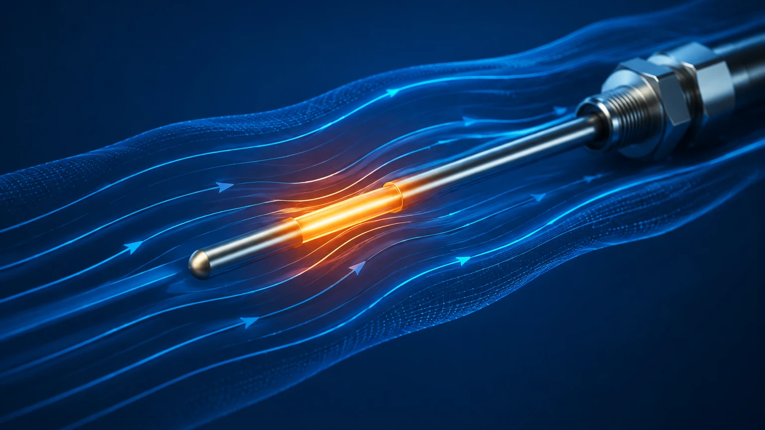
In a typical industrial thermal mass flow meter, the sensor consists of two Resistance Temperature Detectors (RTDs). These are usually made of platinum and are protected by a stainless steel or Hastelloy sheath.
1. The Reference Sensor: This RTD measures the actual temperature of the process gas.
2. The Active (Heated) Sensor: This RTD is supplied with power to maintain a specific temperature higher than that of the reference sensor.
As gas flows past the sensors, the gas molecules carry heat away from the active sensor. The electronics of the meter detect this cooling effect and respond accordingly to maintain the equilibrium or measure the temperature drop.
Operational Modes: Constant Temperature vs. Constant Power
While the underlying thermal mass flow meter working principle remains the same, manufacturers generally employ one of two primary electronic methods to translate heat loss into a flow signal.
1. Constant Temperature Differential
This is the most common method used in modern industrial instruments. The meter's electronics provide a variable amount of power to the heated sensor to maintain a constant temperature difference (ΔT) between the heated sensor and the reference sensor. As the mass flow increases, more heat is carried away, requiring more electrical power to maintain the ΔT. Since the power required is proportional to the mass flow rate, the electrical current used becomes the basis for the flow signal.
2. Constant Power
In this configuration, a fixed amount of electrical power is supplied to the heated sensor. As the gas flow increases, the temperature of the heated sensor decreases because of the cooling effect. The temperature difference between the heated sensor and the reference sensor is measured. In this case, the ΔT is inversely proportional to the mass flow rate. This method is sometimes preferred in very high-temperature applications where maintaining a high ΔT might stress the sensor components.
Key Components and Construction
To ensure reliability in harsh industrial environments, the construction of a thermal mass flow meter must be robust. A standard unit includes the following components:
* Sensor Probes: Typically constructed from 316L Stainless Steel, these house the platinum RTDs. For corrosive gases, specialized coatings or materials like Tantalum are used.
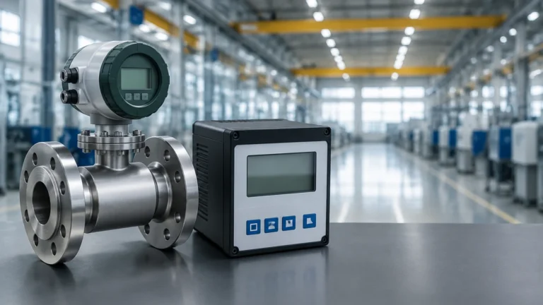
* Flow Body: For small pipe sizes (usually below 50 mm), an "in-line" style flow body is used. This includes a fixed length of pipe with the sensors pre-installed. For larger pipes, an "insertion" style is used, where the probe is inserted through a flange or a compression fitting.
* Transmitter/Electronics: This module performs the bridge circuit calculations, linearizes the signal, and provides outputs such as 4-20mA, pulse, or digital protocols like Modbus and HART.
Technical Selection Criteria
Selecting the right meter requires a deep understanding of the process conditions. Because the thermal mass flow meter working principle depends on the thermal properties of the gas (specifically the specific heat capacity, $C_p$), the meter must be calibrated for the specific gas or gas mixture it will encounter.
| Parameter | Description | Typical Value/Requirement |
| :— | :— | :— |
| Gas Composition | The specific heat of the gas must be known. | Pure gases or stable mixtures. |
| Flow Range | The ratio between maximum and minimum flow. | High turndown (up to 100:1 or more). |
| Pipe Diameter | Determines whether to use in-line or insertion. | In-line (<50mm) / Insertion (>50mm). |
| Accuracy | The allowable margin of error. | Typically ±1% of reading + 0.5% of full scale. |
| Pressure Drop | The resistance the meter adds to the line. | Negligible (no moving parts). |
| Temperature Range | The operating limits of the sensors. | Up to 250°C (standard) or 450°C (high temp). |
When evaluating technology for your facility, it is helpful to Review product options and application support on our Main Page to ensure the hardware matches your specific chemical compatibility and pressure requirements.
Installation Considerations and Best Practices
To achieve the accuracy specified by the manufacturer, the flow profile at the point of measurement must be fully developed and stable. The thermal mass flow meter working principle is sensitive to turbulence, which can cause erratic readings.
Straight Pipe Requirements
Standard installations typically require a minimum of 20 diameters (20D) of straight pipe upstream of the sensor and 5 diameters (5D) downstream. If there are elbows, valves, or reducers closer than this, flow conditioners (honeycombs or perforated plates) may be necessary to straighten the flow.
Orientation
For gas applications, the sensors should ideally be installed in a horizontal pipe. If installed in a vertical pipe, the flow should ideally be upward to prevent moisture from pooling on the sensor tips. In horizontal pipes, the probe should be inserted from the side (3 o'clock or 9 o'clock position) rather than the top or bottom to avoid interference from condensate or sediment.
Moisture and Particulates
The presence of water droplets is the primary enemy of the thermal mass flow meter working principle. If a water droplet hits the heated sensor, it causes a sudden, massive heat transfer as the water evaporates. This is interpreted by the meter as a massive spike in flow, leading to inaccurate data. In saturated gas applications, knock-out pots or heaters may be required upstream.
Limitations and Common Risks
While highly effective, TMFMs are not universal solutions. Engineers should be aware of the following limitations:
1. Gas Composition Shifts: If the gas mixture changes (e.g., a shift in the ratio of Methane to Ethane in natural gas), the thermal properties change, and the meter will report an error. TMFMs are best suited for gases with a consistent composition.
2. Sensor Coating: If the gas is "dirty" and carries oils or resins, these substances can coat the sensor probes. This coating acts as an insulator, slowing the heat transfer and causing the meter to read lower than the actual flow.
3. Low Flow Sensitivity: While TMFMs are excellent at low flow, at zero flow, some heat may still transfer through the gas via natural convection, which can lead to a small "creep" in the reading. Most modern meters include a "low flow cut-off" setting to manage this.
Comparison with Other Technologies
Compared to Differential Pressure (DP) meters or Vortex meters, thermal mass flow meters offer several distinct advantages for gas measurement:
* No Moving Parts: This reduces maintenance and increases the lifespan of the instrument in vibrating industrial environments.
* Direct Mass Flow: Eliminates the cost and complexity of installing separate pressure and temperature transmitters and a flow computer.
* Sensitivity: They can detect leaks and very low velocities that would be below the threshold of a vortex or turbine meter.
Frequently Asked Questions (FAQ)
Q: Does the thermal mass flow meter working principle apply to liquids?
A: While theoretically possible, thermal mass flow meters are almost exclusively used for gases. Liquids have much higher thermal conductivity and heat capacity, making the power requirements for the heated sensor impractical for most industrial flow rates. For liquids, electromagnetic or ultrasonic meters are usually preferred.
Q: How often do these meters need recalibration?
A: In clean gas applications, a TMFM can maintain its calibration for several years. However, in regulated industries or applications with potential sensor coating, an annual calibration check is recommended. Some advanced meters offer "in-situ" calibration validation, allowing the user to check the sensor's health without removing it from the pipe.
Q: Can I use a thermal mass flow meter for oxygen service?
A: Yes, but the meter must be specially cleaned for oxygen service to remove all traces of hydrocarbons (oils/grease) that could ignite in a high-pressure oxygen environment. The materials of construction must also be compatible with oxygen.
Q: What is the impact of high pressure on the measurement?
A: Because the meter measures mass, higher pressure simply means more molecules are passing the sensor. The principle holds true at high pressures, though the physical construction of the probe and the seal (flange rating) must be rated for the process pressure.
Conclusion
The thermal mass flow meter working principle provides a reliable, efficient, and cost-effective way to measure gas mass flow in a wide variety of industrial applications. By understanding the physics of heat transfer and the importance of gas-specific calibration, engineers can select and install these instruments to achieve high precision and long-term stability.
For those looking to integrate these sensors into their automation systems, it is vital to consult with manufacturers who provide robust calibration data and application-specific engineering. To explore a wide range of industrial measurement solutions, including radar, ultrasonic, and flow instruments, you can Review product options and application support by visiting our Main Page.