Thermo-temp
Thermo-temp
In the field of industrial process control, the term "thermo-temp" encapsulates the critical relationship between thermal dynamics and temperature monitoring within level measurement systems. Accurate level detection is rarely a standalone physical measurement; it is an integrated calculation that must account for the thermal state of the medium, the ambient environment, and the structural integrity of the sensor under heat stress. For engineers and plant managers, understanding the thermo-temp profile of a process is the first step in ensuring long-term reliability and safety.
Temperature fluctuations affect the physical properties of liquids and gases, which in turn alters how different sensing technologies perceive the "level" of a tank or vessel. Whether dealing with cryogenic storage or high-pressure steam boilers, the thermal environment dictates the selection of hardware, the calibration of software, and the maintenance intervals of the instrumentation.
Measurement Principles and Thermal Compensation
Before selecting a specific instrument, it is essential to understand how temperature—the "thermo" component—interacts with the physics of various measurement principles. Each technology has a unique sensitivity to thermal changes.
Ultrasonic Level Measurement
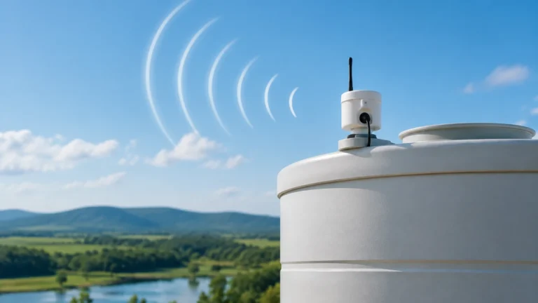
Ultrasonic sensors measure level by emitting sound pulses that reflect off the liquid surface. The time-of-flight is converted into distance. However, the speed of sound in air is highly dependent on temperature. At 0°C (32°F), sound travels at approximately 331.5 m/s, whereas at 40°C (104°F), it increases to about 355 m/s.
Without a built-in thermo-temp compensation probe, an ultrasonic sensor would report significant errors as the vapor space warms or cools. Most modern ultrasonic transmitters include an integrated thermistor to measure the air temperature near the transducer and adjust the distance calculation in real-time. However, in tanks with significant thermal layering (where the top is much hotter than the bottom), a single-point temperature measurement may still result in inaccuracies.
Hydrostatic Level Measurement
Hydrostatic pressure transmitters calculate level based on the formula $P = \rho gh$ (Pressure = density × gravity × height). Temperature is a critical variable here because liquid density ($\rho$) changes with temperature. As a liquid heats up, it typically expands, and its density decreases.
If a hydrostatic sensor is calibrated for water at 20°C (68°F) but the process operates at 80°C (176°F), the pressure reading will be lower for the same physical volume, leading to an underestimation of the actual level. High-end hydrostatic systems often use a dual-input approach, where a separate temperature sensor provides data to a PLC or the transmitter itself to perform density correction based on known fluid tables.
Radar Level Measurement (Non-Contact and GWR)
Radar technology is generally considered the most robust against thermo-temp variations because electromagnetic waves are not significantly affected by the temperature or pressure of the gas phase. However, extreme temperatures can affect the dielectric constant of the medium and, more importantly, the mechanical components of the radar unit.
In high-temperature applications, the focus shifts from signal compensation to physical protection. The antenna and the seals (typically PTFE or ceramics) must be rated for the process temperature to prevent mechanical failure or signal leakage.
Magnetic Level Gauges
Magnetic level gauges rely on a float containing a magnet assembly that moves with the liquid level. The float is engineered to have a specific buoyancy based on the liquid's density. If the thermo-temp profile of the process exceeds the design parameters, the liquid's density may drop to a point where the float sinks or sits lower in the fluid, causing a measurement offset. Furthermore, extreme heat can affect the magnetic strength of the internal components if they exceed their Curie temperature, though industrial magnets are usually rated far above standard process limits.
Comparing Technologies: A Thermo-Temp Selection Matrix
When evaluating level measurement solutions, engineers must match the instrument's thermal limits with the process requirements. The following table provides a general guideline for common industrial technologies.
| Technology | Typical Temp Range | Accuracy Impact of Temp | Primary Thermal Concern |
| :— | :— | :— | :— |
| Ultrasonic | -40°C to 95°C | High | Speed of sound variation in vapor space. |
| Hydrostatic | -20°C to 120°C* | Medium | Fluid density changes (expansion/contraction). |
| Radar (80GHz) | -60°C to 250°C+ | Low | Seal integrity and electronics cooling. |
| Magnetic Gauge | -196°C to 450°C | Low/Medium | Float buoyancy and chamber expansion. |
| Level Switches | -50°C to 200°C | Low | Material fatigue and electrical insulation. |
*Note: High-temperature hydrostatic versions utilize capillary tubes and remote seals to protect the sensor diaphragm.*
Engineering Considerations for High-Temperature Applications
In environments where the thermo-temp demands are extreme, standard off-the-shelf instruments may fail prematurely. Engineering for these scenarios requires a focus on heat dissipation and material science.
1. Remote Electronics: For processes exceeding 100°C (212°F), it is often advisable to use split-architecture sensors. By separating the sensing element (antenna or probe) from the transmitter electronics via a high-temperature cable, the sensitive digital components are kept in a cooler ambient environment.
2. Cooling Fins and Heat Dissipators: For radar and ultrasonic transmitters mounted directly on a hot vessel, cooling fins can be integrated into the mounting flange. These fins increase the surface area for convective cooling, preventing process heat from conducting upward into the sensor housing.
3. Wetted Material Selection: Standard O-rings and gaskets have specific thermal limits. Viton, Kalrez, and graphite-based seals are often required for high thermo-temp applications. Similarly, the choice of metal for the probe—such as 316L Stainless Steel, Hastelloy, or Monel—must account for thermal expansion rates to prevent mechanical binding in narrow nozzles.
For more detailed technical specifications on sensor materials and thermal ratings, you may visit our Main Page.

Installation Best Practices for Thermal Stability
Proper installation is as important as sensor selection when managing thermo-temp challenges. Even the most accurate sensor will provide poor data if installed in a location with extreme thermal gradients.
Avoiding Thermal Plumes
In heated vessels, avoid mounting sensors directly above steam inlets or heating coils. The rising thermal plumes can create localized turbulence and density variations that interfere with ultrasonic and radar signals. If possible, install the sensor in a stilling well or a bypass chamber to isolate the measurement area from the main process turbulence.
Insulation and Heat Tracing
In outdoor installations or cold climates, "thermo-temp" management often involves keeping the process fluid from freezing or becoming too viscous. While insulating the tank is standard, the instrument nozzle must also be insulated. However, be careful not to insulate the electronics housing, as this can trap heat generated by the sensor's internal circuitry, leading to electronic failure.
Nozzle Length and Diameter
In high-temperature radar applications, the nozzle length should be minimized to prevent the buildup of condensate, which can occur if the nozzle is cooler than the process vapor. Conversely, in very hot applications, a longer nozzle might be used to provide a "thermal buffer" between the process and the sensor, provided the radar beam has enough clearance to avoid interference.
Limitations and Critical Risks
While technology has advanced, there are inherent limitations to managing thermo-temp factors in level measurement:
* Thermal Shock: Rapid changes in temperature (e.g., during a Clean-In-Place or CIP cycle in food processing) can cause ceramic diaphragms to crack or metal components to warp. Sensors must be rated for the rate of temperature change, not just the absolute maximum temperature.
* Non-Linear Density: For complex chemical mixtures, density changes with temperature may not be linear. In these cases, simple hydrostatic compensation is insufficient, and more advanced technologies like Guided Wave Radar (GWR) are preferred.
* Ambient Temperature Extremes: Often, the failure point is not the process temperature but the ambient temperature. If a transmitter is located in a desert environment or near a furnace, the housing can exceed its 85°C (185°F) limit even if the process is relatively cool.
Frequently Asked Questions (FAQ)
Q: Can I use an ultrasonic sensor for boiling liquids?
A: It is generally not recommended. The heavy steam and turbulence associated with boiling create a non-homogeneous medium for the sound waves, and the extreme thermo-temp gradients in the vapor space make accurate compensation nearly impossible. Radar is a much better choice for boiling applications.
Q: How often should I calibrate my level meter for temperature?
A: Calibration should be checked whenever there is a significant change in the seasonal ambient temperature or if the process recipe changes. For hydrostatic systems, an annual verification of the fluid density vs. temperature curve is best practice.
Q: Does temperature affect the dielectric constant in radar measurement?
A: Yes, for many liquids, the dielectric constant decreases as temperature increases. However, for most non-contact radar applications, this change is not significant enough to lose the signal unless the liquid is already a very poor reflector (low dielectric).
Q: What is the benefit of a remote seal in hydrostatic measurement?
A: A remote seal uses a capillary tube filled with a transmission fluid (like silicone oil) to separate the sensor from the hot process. This allows the transmitter to be mounted in a cool location while still accurately sensing the pressure at the hot tank wall.
By carefully considering the thermo-temp dynamics of your specific application, you can select a level measurement system that provides accurate data and a long service life. For assistance in selecting the right technology for your thermal environment, please refer to the resources available on our Main Page.