Thermowell Thermometer
Thermowell Thermometer
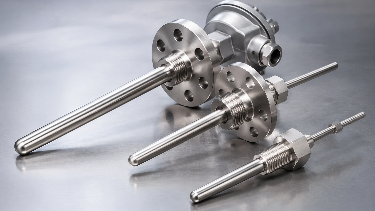
In industrial process control, temperature measurement is rarely as simple as placing a sensor into a fluid. High pressures, corrosive chemicals, and high-velocity flows can easily destroy delicate sensing elements. This is where the thermowell thermometer assembly becomes essential. A thermowell is a cylindrical fitting used to protect temperature sensors installed in industrial processes. It acts as a barrier between the process media and the sensing element, allowing for sensor replacement or maintenance without opening the vessel or pipe.
For engineers managing complex systems, understanding the synergy between temperature and other variables like level is crucial. For instance, accurate level measurement often depends on temperature data to compensate for fluid density changes. To explore a comprehensive range of industrial instrumentation, you can visit the Main Page of our product catalog.
Fundamental Principles of Thermowell Temperature Measurement
The operation of a thermowell thermometer relies on the principles of heat transfer—specifically conduction and convection. The process involves three distinct stages of thermal energy movement:
1. Convection: Heat is transferred from the moving process fluid (liquid or gas) to the outer surface of the thermowell wall.
2. Conduction: Heat travels through the solid material of the thermowell wall to the internal cavity.
3. Final Transfer: The heat moves from the inner wall of the thermowell to the actual temperature sensor (RTD, thermocouple, or bimetallic element) via conduction (if in contact) or radiation and convection (if there is an air gap).
Thermal Equilibrium and Response Time
The goal of a thermowell thermometer is to reach thermal equilibrium, where the sensor temperature matches the process temperature. However, the mass of the thermowell introduces "thermal lag." A thicker thermowell provides better protection but slows down the response time. Engineers must balance the need for structural integrity with the requirement for real-time data accuracy.
Stem Conduction Error
A common challenge in thermowell design is stem conduction error. This occurs when heat flows along the length of the thermowell toward the cooler (or hotter) ambient environment outside the pipe. If the insertion length is too short, the sensor may report a temperature that is influenced more by the pipe wall or ambient air than by the process fluid itself.
Types of Thermowells and Sensors
Selecting the right thermowell thermometer requires matching the protective housing with the appropriate sensing technology.
Sensor Types
* RTDs (Resistance Temperature Detectors): Known for high accuracy and stability, typically using platinum elements (Pt100 or Pt1000). They are ideal for precise process control.
* Thermocouples: Preferred for extremely high temperatures and rugged applications. They operate on the Seebeck effect, generating a voltage proportional to the temperature difference between two dissimilar metals.
* Bimetallic Thermometers: Mechanical gauges that use the expansion of two different metals to move a pointer. These are often used for local indication without the need for external power.
Thermowell Connection Styles
* Threaded: Screwed directly into a tapped fitting on the pipe or vessel. These are common in lower-pressure applications.
* Flanged: Bolted to a mating flange on the process equipment. These are the standard for high-pressure, high-temperature, and highly corrosive environments.
* Socket Weld: Welded into place for a permanent, leak-proof connection. These are frequently used in high-pressure steam lines where maintenance access is less critical than structural integrity.
Critical Selection Criteria for Industrial Applications
When specifying a thermowell thermometer, several factors must be evaluated to ensure both safety and performance.
Material Compatibility
The thermowell material must withstand the chemical nature of the process fluid. Common materials include:
* 316 Stainless Steel: The standard for water treatment and general chemical use.
* Hastelloy C-276: Used for highly corrosive acids.
* Monel 400: Ideal for seawater and hydrofluoric acid applications.
Wake Frequency and Velocity
As fluid flows past a thermowell, it creates vortices (the Von Kármán vortex street). If the frequency of these vortices matches the natural resonance frequency of the thermowell, it can lead to catastrophic vibration failure. Engineers use the ASME PTC 19.3 TW standard to calculate the safe limits for insertion length and diameter based on fluid velocity and density.
Selection Table: Thermowell Comparison
| Feature | Threaded Thermowell | Flanged Thermowell | Socket Weld Thermowell |
| :— | :— | :— | :— |
| Pressure Rating | Medium (up to 200 bar / 3000 psi) | High (Class 150 to 2500) | Very High |
| Ease of Replacement | High | Medium | Low (Requires cutting) |
| Leak Risk | Potential at threads | Low (with proper gasket) | Lowest (Hermetic) |
| Typical Industry | HVAC, Food & Beverage | Oil & Gas, Chemical | Power Generation, Steam |
The Intersection of Temperature and Level Measurement
In many industrial sectors, temperature measurement is not an isolated requirement. It is a secondary variable that ensures the accuracy of primary measurements like liquid level. For example, in hydrostatic level measurement, the sensor measures the pressure exerted by a liquid column. Since the density of a liquid changes with temperature, a thermowell thermometer is often installed nearby to provide the data necessary for density compensation.
Similarly, in radar or ultrasonic level applications, temperature variations in the vapor space can affect the speed of the signal (though radar is significantly less affected than ultrasonic). By integrating reliable temperature sensing with advanced level instruments, operators can achieve a higher degree of process automation and safety. For more information on how these technologies work together, visit the Main Page.
Installation and Maintenance Best Practices
Correct installation is vital to minimize measurement errors and extend the life of the instrument.
1. Insertion Length (U-Length): A general rule of thumb is that the thermowell should extend into the fluid at least 10 times its outer diameter to minimize stem conduction error. In pipes, the tip should ideally be at the center of the flow.
2. Orientation: In small-diameter pipes, thermowells should be installed at an elbow or at an angle (45 degrees) against the flow to maximize the surface area in contact with the fluid.
3. Lagging Extension: If the pipe is insulated, the thermowell should have a "T-length" (extension) that allows the connection head to sit outside the insulation, preventing the electronics from overheating.
4. Heat Transfer Paste: To improve response time, a thermal conductive paste can be used inside the thermowell to fill the air gap between the sensor and the inner wall. However, this should be avoided in extremely high-temperature applications where the paste might bake and seize the sensor.
Risks, Limitations, and Mitigation Strategies
Despite their robustness, thermowell thermometers have limitations that must be managed:
* Corrosion and Erosion: High-velocity slurries can erode the wall of the thermowell over time. Regular ultrasonic thickness testing or visual inspections during shutdowns are recommended.
* Response Lag: In processes with rapid temperature fluctuations, the delay caused by the thermowell can lead to "hunting" in PID control loops. Using a tapered thermowell design can reduce mass at the tip and improve response speed.
* Vibration Failure: If a wake frequency calculation indicates a risk, the engineer may need to shorten the insertion length, increase the root diameter, or use a "Scruton" (helical) fairing to disrupt vortex formation.
Frequently Asked Questions (FAQ)
Q: How often should a thermowell be inspected?
A: This depends on the process. In non-corrosive water applications, every 3-5 years may suffice. In high-velocity steam or corrosive chemical lines, annual inspections or even continuous monitoring for vibration may be necessary.
Q: Can I use a thermowell with a bimetallic thermometer?
A: Yes, bimetallic thermometers are frequently paired with thermowells for local temperature monitoring in tanks and piping. Ensure the stem length of the thermometer matches the U-length of the thermowell.
Q: What is the difference between a tapered and a straight thermowell?
A: A straight thermowell has a uniform diameter. A tapered thermowell has a larger diameter at the base (root) and a smaller diameter at the tip. Tapered designs offer a better strength-to-weight ratio and faster response times in high-velocity flows.
Conclusion: Confirming Project Requirements
Before finalizing a thermowell thermometer specification, project managers and engineers should confirm the following data points:
* Maximum Process Pressure and Temperature: Ensure the material and connection type are rated for the extremes.
* Fluid Velocity: Perform a wake frequency calculation for all flow-line installations.
* Chemical Composition: Verify that the thermowell material is compatible with all process constituents, including cleaning agents (CIP).
* Integration Needs: Determine if the temperature signal needs to be integrated into a level measurement system or a broader DCS/SCADA network.
By carefully selecting and installing thermowell thermometers, industrial facilities can ensure accurate data, protect their instrumentation investment, and maintain a safe operating environment.