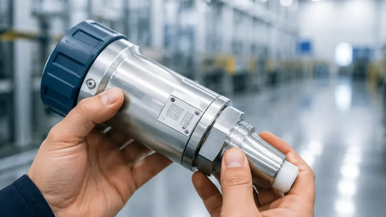
Transmitter Sensor
Transmitter Sensor
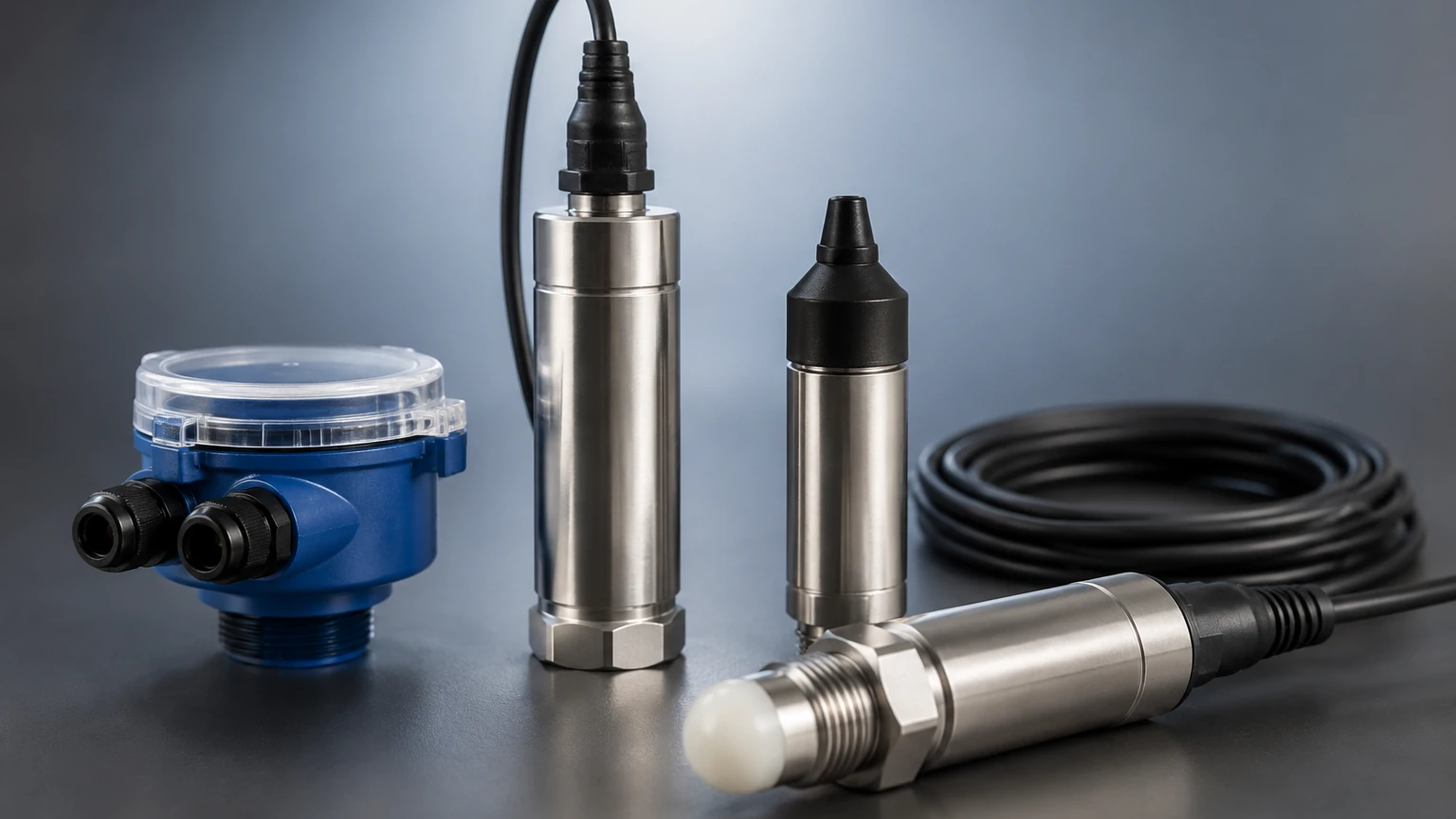
In the field of industrial process control, the term "transmitter sensor" refers to an integrated assembly designed to detect a physical quantity—such as liquid level, pressure, or temperature—and convert that detection into a standardized electrical signal. While the "sensor" is the primary element that interacts with the medium, the "transmitter" is the electronic component that processes the raw signal into a format suitable for long-distance transmission to a Programmable Logic Controller (PLC) or Distributed Control System (DCS).
For engineers and procurement professionals, choosing the correct transmitter sensor is a critical step in ensuring operational safety, inventory accuracy, and process efficiency. This guide focuses specifically on level measurement technologies, exploring the physical principles, selection criteria, and installation requirements necessary for successful deployment in industries ranging from water treatment to chemical processing.
Understanding the Transmitter Sensor in Industrial Level Measurement
A modern level transmitter sensor typically outputs a 4-20 mA analog signal, often with a digital overlay like HART (Highway Addressable Remote Transducer), or utilizes digital protocols such as RS485 Modbus. This allows the instrument to communicate not just the level value, but also diagnostic data regarding the health of the sensor itself.
In industrial environments, these devices must withstand harsh conditions, including corrosive chemicals, extreme temperatures, and high pressures. The integration of the sensing element and the transmitter electronics into a single housing reduces wiring complexity and minimizes signal noise, which is essential for maintaining high precision in automated systems. To explore a comprehensive range of these instruments, engineers can refer to the Main Page of professional equipment catalogs to compare specific model capabilities.
Core Measurement Principles and Technologies
Before selecting a transmitter sensor, it is essential to understand the underlying physics of the different technologies available. Each principle has specific strengths and limitations based on the physical properties of the medium and the environment.
Radar Level Measurement (Time-of-Flight)
Radar transmitter sensors use high-frequency electromagnetic waves (typically in the 26 GHz or 80 GHz range). The sensor emits a microwave pulse that travels to the surface of the medium, reflects, and returns to the receiver. The transmitter calculates the distance based on the time it takes for the pulse to travel (Time-of-Flight).
- Non-contact: The sensor does not touch the liquid, making it ideal for corrosive or hygienic applications.
- Versatility: Radar is largely unaffected by temperature, pressure, or vacuum conditions.
Ultrasonic Level Measurement
Ultrasonic sensors function similarly to radar but use sound waves instead of electromagnetic waves. The transducer emits an ultrasonic pulse (usually around 40 kHz) that reflects off the liquid surface.
- Medium Dependency: Since sound requires a medium (air) to travel, the accuracy of an ultrasonic transmitter sensor is highly dependent on the air temperature and density. Most units include integrated temperature compensation.
- Application: Best suited for water treatment and simple liquid storage where foam and steam are not present.
Hydrostatic Pressure Measurement
This technology relies on the principle that the pressure at the bottom of a liquid column is directly proportional to the height of that column. The formula used is $P = \rho \cdot g \cdot h$, where $P$ is pressure, $\rho$ (rho) is the density of the liquid, $g$ is gravity, and $h$ is the height.
- Contact Method: The sensor is either submerged in the liquid or mounted to a flange at the bottom of the tank.
- Reliability: It is a robust method for vented tanks but requires precise knowledge of the liquid's density.
Magnetic Level Gauges and Transmitters
Magnetic systems use a float containing a permanent magnet that moves with the liquid level inside a bypass chamber. An external transmitter sensor rod, often using reed switches or magnetostrictive technology, detects the position of the float.
- Visual + Electronic: Provides a local visual indication alongside the electronic signal.
- Safety: Excellent for high-pressure or toxic liquids where a direct tank penetration for a sensor is undesirable.
Key Selection Criteria for Engineering Projects
Selecting the right transmitter sensor requires a detailed analysis of the process environment. Engineers should confirm the following parameters before procurement:
1. Media Characteristics: Is the liquid corrosive, viscous, or prone to crystallization? For example, a PTFE-coated radar sensor is preferred for concentrated acids, while a hydrostatic sensor might fail if the medium clogs the diaphragm.
2. Process Conditions: What are the maximum and minimum operating temperatures and pressures? Ultrasonic sensors typically fail in high-pressure environments (above 3 bar / 43.5 PSI), whereas radar can handle significantly higher loads.
3. Accuracy Requirements: Standard industrial applications may require ±5 mm accuracy, while custody transfer or high-value chemical dosing may require ±1 mm.
4. Output and Connectivity: Does the control system require a 4-20 mA loop, or is a digital RS485/Modbus interface needed for a multi-drop network?
5. Tank Geometry: Internal obstructions like agitators, heating coils, or ladders can interfere with non-contact signals (radar and ultrasonic). In such cases, guided wave radar or hydrostatic sensors may be more appropriate.
Practical Selection Table: Technology Comparison
The following table provides a quick reference for comparing the most common transmitter sensor technologies used in industrial level measurement.
| Technology | Best For | Limitations | Typical Accuracy | Max Range |
| :— | :— | :— | :— | :— |
| Radar (80 GHz) | Small tanks, corrosive liquids, solids | Higher initial cost | ±1 mm to ±2 mm | Up to 120m |
| Ultrasonic | Water, wastewater, open channels | Affected by foam, steam, and vacuum | ±0.25% of range | Up to 30m |
| Hydrostatic | Deep wells, vented tanks, oils | Sensitive to density changes | ±0.1% to ±0.5% | Up to 200m |
| Guided Wave Radar | Low dielectric liquids, foam | Contacting (cable or rod) | ±2 mm | Up to 75m |
| Magnetic | High-pressure boilers, toxic media | Moving parts (float) | ±5 mm to ±10 mm | Up to 6m |
Installation Guidelines and Best Practices
Even the most advanced transmitter sensor will provide inaccurate data if installed incorrectly. Proper mounting is essential for signal integrity.
Positioning for Non-Contact Sensors
For radar and ultrasonic sensors, the unit should be mounted away from the tank wall (typically at least 200 mm or 1/6th of the tank diameter) to avoid signal interference from wall reflections. It must also be positioned away from the liquid inlet to prevent the sensor from detecting the falling stream instead of the actual level.
Dead Zones (Blocking Distance)
Every ultrasonic and radar transmitter sensor has a "dead zone" or "blocking distance" immediately below the sensor face. If the liquid level rises into this zone, the sensor cannot provide a reading. Engineers must ensure the sensor is mounted high enough so that the maximum liquid level never enters this area.
Hydrostatic Venting
Submersible hydrostatic sensors use a vented cable to compensate for changes in atmospheric pressure. It is vital that the vent tube remains clear and is protected from moisture; otherwise, the sensor will report an incorrect level as weather patterns change.
Avoiding Obstructions
When using non-contact sensors, ensure the signal beam path is clear of agitators, spray balls, or structural beams. If obstructions are unavoidable, many modern transmitters offer "false echo suppression" software, allowing the user to map out and ignore reflections from fixed internal structures.
Common Risks and Technical Limitations
While transmitter sensors are highly reliable, certain conditions can lead to measurement errors or device failure:
* Foam Accumulation: Heavy, dense foam can absorb ultrasonic and radar signals, leading to a "loss of echo" error. In these scenarios, a hydrostatic transmitter or a guided wave radar (which uses a physical probe to guide the signal) is often a better choice.
* Vapor and Condensation: In closed tanks, condensation can form on the face of an ultrasonic transducer, blocking the sound pulse. Radar is less affected by this, but heavy steam can still attenuate high-frequency signals.
* Dielectric Constant ($ε_r$): Radar relies on the dielectric constant of the liquid. Very low dielectric liquids (like certain oils or liquefied gases) reflect less energy. If the $ε_r$ is below 1.4, a guided wave radar or a mechanical system may be required.
* Density Fluctuations: Since hydrostatic sensors measure weight, any change in the liquid's density (caused by temperature shifts or mixing different chemicals) will result in a level error unless the transmitter is recalibrated or paired with a temperature sensor for compensation.
Frequently Asked Questions (FAQs)
Q: Can I use one transmitter sensor for different types of liquids?
A: It depends on the technology. Radar and ultrasonic sensors are generally liquid-independent as long as the surface reflects the signal. However, hydrostatic sensors must be recalibrated if the liquid density changes significantly.
Q: What is the difference between a level switch and a transmitter sensor?
A: A level switch provides a binary output (on/off) at a specific point (e.g., high-level alarm). A transmitter sensor provides continuous measurement across the entire range of the tank.
Q: How often do these sensors need calibration?
A: Most modern solid-state sensors (radar/ultrasonic) are very stable and may only require verification once a year. Hydrostatic sensors may require more frequent calibration if the diaphragm is subject to mechanical wear or coating.
Q: Is 80 GHz radar always better than 26 GHz?
A: 80 GHz offers a narrower beam angle, which is better for small tanks or tanks with many internal obstructions. However, 26 GHz can be more effective in extremely dusty environments or where very heavy steam is present.
Conclusion
The successful implementation of a transmitter sensor system requires a balance between technological capability and application requirements. By understanding the measurement principles—whether it be the electromagnetic pulses of radar or the pressure-based calculations of hydrostatic sensors—engineers can mitigate risks and ensure long-term reliability.
For those looking to specify equipment for a new project or replace an aging system, reviewing product options and application support on the Main Page is a recommended next step to ensure the selected hardware aligns with the specific chemical and physical demands of the process.