Turbidity Probes
Turbidity Probes
In industrial process control and environmental monitoring, the clarity of a liquid is often as critical as its volume or pressure. Turbidity probes are the primary instruments used to quantify the concentration of suspended solids within a fluid by measuring the degree to which light is scattered or absorbed. For engineers and plant managers, selecting the correct turbidity measurement technology is essential for ensuring product quality, regulatory compliance, and equipment protection.
While level measurement instruments—such as those found on the Main Page—track the quantity of material in a tank, turbidity probes provide insight into the physical characteristics of that material. This guide explores the measurement principles, selection criteria, and installation requirements for industrial-grade turbidity probes.
Understanding Turbidity Measurement Principles
Turbidity is not a direct measurement of the mass of suspended solids; rather, it is an optical property. When light passes through a liquid containing suspended particles (such as silt, clay, organic matter, or chemical precipitates), the particles interfere with the light's path. Probes utilize different optical geometries depending on the expected concentration of these particles.
1. Nephelometry (90° Scatter)
Nephelometry is the most common method for measuring low to medium turbidity levels. The probe emits a light beam into the medium, and a detector is positioned at a 90-degree angle to the light source. This method measures the light scattered by particles. It is highly sensitive to small particles and is the standard for potable water applications. Most nephelometric probes follow the ISO 7027 standard, which specifies an infrared light source (860 nm) to minimize interference from the color of the liquid.
2. Light Attenuation (Transmission)
In high-turbidity environments, so much light is scattered that the 90-degree sensor becomes saturated or the light cannot penetrate deep enough into the medium. Transmission probes measure the loss of light intensity as it travels through a fixed path length to a detector directly opposite the source (180 degrees). This principle is typically used for monitoring high concentrations of suspended solids, such as in wastewater sludge or chemical slurries.
3. Backscatter (135° to 180° Scatter)
For extremely high concentrations where the liquid is nearly opaque, backscatter probes are employed. The light source and detector are located on the same plane or at an obtuse angle. The sensor measures the light reflected back from the particles near the sensor head. This is common in industrial processes involving thick pulps or heavy industrial waste.
Key Technical Specifications and Evaluation Criteria
When evaluating turbidity probes for industrial use, several technical parameters must be harmonized with the specific process conditions. Selecting a probe based solely on price often leads to high maintenance costs or frequent sensor failure.
Measurement Range and Units
Turbidity is measured in various units, the most common being NTU (Nephelometric Turbidity Units) and FNU (Formazin Nephelometric Units). For high-solids applications, units like mg/L, g/L, or %TS (Total Solids) are used.
* Low Range: 0 to 10 NTU (Drinking water, filtered process water).
* Mid Range: 0 to 1,000 NTU (Surface water, industrial effluent).
* High Range: 0 to 10,000+ NTU (Sludge, chemical concentrates).
Light Source Selection
* Infrared (IR) LED: Operates at 860 nm. It is preferred for colored liquids because the light is not absorbed by the color of the fluid, only scattered by particles. It complies with ISO 7027.
* White Light (Tungsten): Complies with EPA 180.1 standards. It is more sensitive to very small particles but is susceptible to interference from the color of the sample.
Material Compatibility
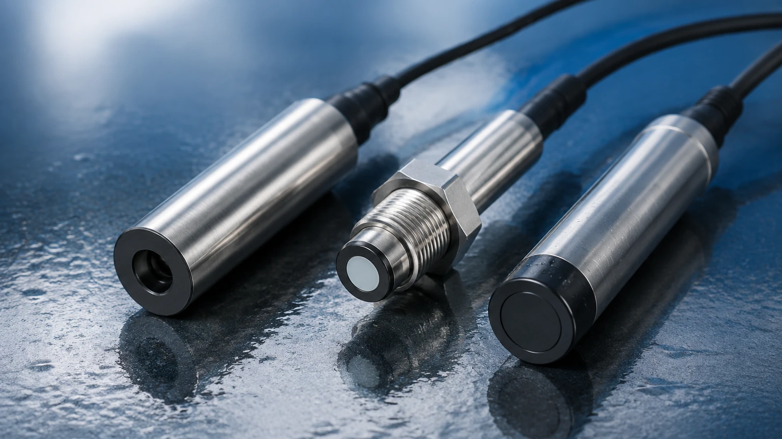
The probe body and optical windows must withstand the chemical environment. Common materials include:
* Body: 316L Stainless Steel, PVC, or Titanium for corrosive environments.
* Optical Window: Sapphire glass (highly scratch-resistant) or Quartz.
* Seals: FKM (Viton) or EPDM.
Selection Table for Industrial Turbidity Probes
The following table provides a general reference for selecting probe types based on typical industrial applications.
| Application Type | Expected Range | Recommended Principle | Preferred Light Source |
| :— | :— | :— | :— |
| Potable Water Treatment | 0–5 NTU | Nephelometric (90°) | IR or White Light |
| Effluent Monitoring | 0–500 NTU | Nephelometric | IR LED |
| Cooling Water Loop | 0–100 NTU | Nephelometric | IR LED |
| Wastewater Sludge | 1,000–50,000 mg/L | Attenuation / Backscatter | IR LED |
| Chemical Processing | Variable | Backscatter | Application Specific |
| Food & Beverage (CIP) | High/Phase change | Backscatter | IR LED |
Installation Guidelines and Best Practices
The physical placement of turbidity probes significantly impacts the accuracy and reliability of the data. Unlike level transmitters, which often measure from the top of a vessel, turbidity probes are usually in direct contact with the flowing process.
1. Orientation and Flow
Probes should be installed in a location with constant flow to prevent sediment from settling on the sensor face. In pipe installations, the probe should be positioned on the side (3 o'clock or 9 o'clock position) rather than the top or bottom. Installing at the top risks interference from air bubbles, while the bottom risks burial by heavy sediments.
2. Avoiding Air Bubbles
Air bubbles are the primary enemy of optical turbidity measurement. A bubble reflects light exactly like a solid particle, leading to false high readings. To mitigate this:
* Install probes in vertical pipes with upward flow.
* Maintain sufficient backpressure to keep gases dissolved.
* Use a de-bubbler or stilling well if the process is prone to entrained air.
3. Ambient Light Interference
While modern probes use modulated light to filter out ambient noise, intense direct sunlight or strong artificial lighting can still saturate the detector. In open channels or tanks, use a sunshade or install the probe at a depth where ambient light cannot reach the sensor head (typically >300 mm).
4. Process Connections
Industrial probes are available with various mounting options:
* Immersion: For open tanks or channels, using a mounting bracket and extension pipe.
* Flow-through: For small-diameter bypass lines where the sample is diverted from the main process.
* In-line: Using a flange or hygienic tri-clamp connection for direct pipe mounting.
Common Risks, Limitations, and Maintenance
Even the most advanced turbidity probes require a maintenance strategy to account for the harsh realities of industrial fluids.
Fouling and Bio-growth
In wastewater or organic processes, a biofilm or scale can form on the optical window. This "fouling" causes the baseline reading to drift upward. To combat this, many industrial probes are equipped with an integrated cleaning system, such as:
* Mechanical Wipers: A small rubber blade that periodically wipes the window.
* Ultrasonic Cleaning: High-frequency vibrations that prevent particles from adhering.
* Air/Water Jets: Using compressed air or water to blast debris off the sensor.
Color Interference
If the liquid changes color (e.g., from clear to yellow), a white-light sensor may interpret the color absorption as turbidity. Using an infrared light source at 860 nm is the standard engineering solution to isolate turbidity from color changes.
Calibration Requirements
Turbidity is a relative measurement. Probes must be calibrated using a primary standard, typically Formazin. Formazin is a synthetic polymer that produces a repeatable light-scattering effect. For routine field checks, secondary standards (such as stable gel suspensions or specialized plastic cubes) are used to verify that the probe has not drifted.
Integration with Process Automation
In a complete industrial automation setup, turbidity data is rarely used in isolation. For example, in a sedimentation tank, an ultrasonic level transmitter (as detailed on the Main Page) might track the height of the sludge blanket, while a turbidity probe monitors the clarity of the supernatant water above it.
Integrating these sensors into a PLC (Programmable Logic Controller) via 4-20mA, Modbus RS485, or HART protocols allows for automated chemical dosing. If the turbidity exceeds a set threshold, the system can automatically increase the coagulant dosage or divert the flow to a holding tank for reprocessing.
Frequently Asked Questions (FAQs)
Q: How often should I calibrate my turbidity probe?
A: This depends on the application. In clean water, a quarterly check is often sufficient. In high-fouling wastewater, monthly calibration and weekly cleaning inspections are recommended.
Q: Can turbidity probes measure the concentration of oil in water?
A: While turbidity probes can detect the presence of oil emulsions, they are not specific to oil. They will measure any suspended matter. For specific oil-in-water measurement, fluorescence-based sensors are more appropriate.
Q: What is the difference between NTU and FNU?
A: NTU (Nephelometric Turbidity Units) typically refers to measurements made with a white light source (EPA 180.1), while FNU (Formazin Nephelometric Units) refers to measurements made with an infrared light source (ISO 7027). If both use the same optical geometry and calibration standard, the values are often numerically similar, but the units indicate the underlying technology.
Q: Can I use a turbidity probe in high-temperature fluids?
A: Most standard probes are rated up to 50°C (122°F). For high-temperature applications, such as condensate monitoring, specialized probes with cooling jackets or high-temperature rated electronics and seals (up to 90°C or higher) must be specified.
Conclusion
Turbidity probes are indispensable tools for maintaining process efficiency and environmental safety. By understanding the optical principles of nephelometry and attenuation, and by accounting for variables like air bubbles and fouling, engineers can select a measurement solution that provides long-term reliability. When paired with robust level measurement and control systems, these probes ensure that industrial processes remain within their specified quality parameters.