Ultra Flow Meter
Ultra Flow Meter
In the landscape of industrial process control, the ultra flow meter—more technically known as the ultrasonic flow meter—has become a cornerstone for non-intrusive liquid and gas measurement. Unlike traditional mechanical meters that rely on moving parts subject to wear and tear, these instruments utilize sound waves to determine velocity. This article provides a comprehensive technical overview of ultrasonic measurement principles, selection criteria, and installation requirements for engineers and procurement professionals seeking reliable flow solutions.
Understanding Ultrasonic Flow Measurement Principles
Before selecting an ultra flow meter, it is essential to understand the two primary physical principles used to derive flow data: Transit-Time and Doppler Effect. Both methods utilize transducers to send and receive ultrasonic signals, but they are applied to different fluid conditions.
Transit-Time Principle
Transit-time ultra flow meters operate by measuring the time difference between an ultrasonic pulse traveling with the flow and one traveling against it. Two transducers are mounted on the pipe, acting as both transmitters and receivers.
When the fluid is moving, the pulse traveling downstream (with the flow) reaches the second transducer faster than the pulse traveling upstream (against the flow). The time difference (Δt) is directly proportional to the velocity of the fluid. This method is highly accurate and is the industry standard for clean liquids, such as treated water, chemicals, and light oils. For those managing complex industrial systems, integrating these meters with advanced level measurement tools found on the Main Page ensures a holistic approach to process monitoring.
Doppler Effect Principle
The Doppler ultra flow meter relies on the frequency shift of an ultrasonic signal reflected off moving discontinuities in the fluid, such as suspended solids or entrained air bubbles. The transducer emits a sound wave at a known frequency; when this wave hits a moving particle, it reflects back at a different frequency. The shift in frequency is proportional to the velocity of the particles. This method is specifically designed for "dirty" liquids, slurries, and aerated fluids where transit-time signals would be blocked or scattered.
Types of Ultra Flow Meters: Inline vs. Clamp-on
Industrial applications generally dictate the physical form factor of the meter. Choosing between inline and clamp-on models depends on the required accuracy, budget, and whether the process can be interrupted for installation.
Inline Ultrasonic Flow Meters
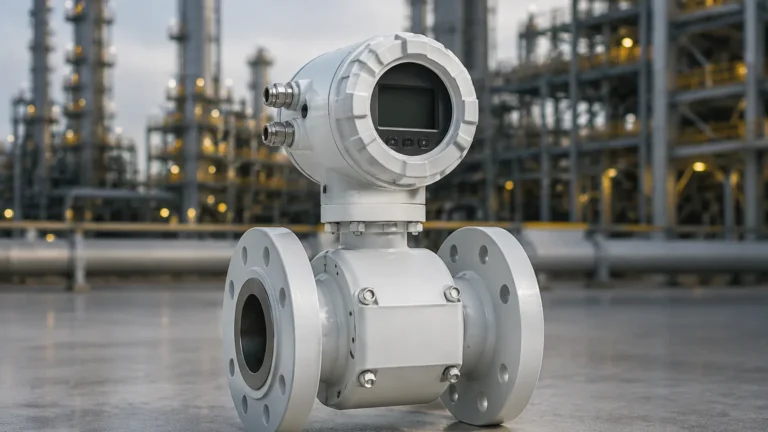
Inline meters are integrated directly into the piping system via flanges or threaded connections. The transducers are in direct contact with the fluid or are mounted behind a protective window.
- Advantages: Highest accuracy (often 0.5% or better), factory-calibrated as a single unit, and less sensitive to pipe wall conditions.
- Disadvantages: Requires pipe cutting, process downtime for installation, and higher initial hardware costs for large pipe diameters.
Clamp-on Ultrasonic Flow Meters
Clamp-on ultra flow meters are mounted to the exterior of the pipe. The ultrasonic signal passes through the pipe wall, through the fluid, and back through the pipe wall to the receiver.
- Advantages: Zero process downtime, no risk of leakage or contamination, and highly portable. They are particularly cost-effective for large pipe diameters (e.g., >300 mm / 12 inches).
- Disadvantages: Accuracy is dependent on pipe wall consistency and proper coupling; typically ranges from 1% to 3%.
Key Evaluation Criteria for Industrial Applications
Selecting the correct ultra flow meter requires a detailed analysis of the process environment. The following table provides a baseline for comparing the two primary technologies based on common industrial parameters.
| Parameter | Transit-Time Meter | Doppler Meter |
| :— | :— | :— |
| Fluid Type | Clean liquids, water, oils | Slurries, wastewater, aerated fluids |
| Suspended Solids | < 2% by volume | > 100 ppm (minimum size ~100 microns) |
| Pipe Size Range | 10 mm to 5000 mm (0.5" to 200") | 12.5 mm to 5000 mm (0.5" to 200") |
| Typical Accuracy | ±0.5% to ±1.0% of flow rate | ±2.0% to ±5.0% of full scale |
| Flow Velocity | 0.01 to 12 m/s (0.03 to 40 ft/s) | 0.05 to 10 m/s (0.15 to 30 ft/s) |
| Maintenance | Very Low | Low |
Pipe Material and Liner Considerations
For clamp-on ultra flow meters, the pipe material is a critical factor. Sound travels differently through carbon steel, stainless steel, PVC, and ductile iron. If the pipe has a liner (e.g., cement, rubber, or glass), the liner must be sonically bonded to the pipe wall. Air gaps between the pipe and the liner will reflect the ultrasonic signal, rendering the meter inoperable.
Installation Best Practices for Accuracy
Even the most advanced ultra flow meter will provide inaccurate data if installed poorly. Engineers must adhere to strict piping geometry and mounting guidelines to ensure a stable flow profile.
Straight Pipe Run Requirements
Ultrasonic meters require a fully developed laminar flow profile. Turbulence caused by elbows, valves, or pumps can distort the sound waves.
- Upstream: A minimum of 10 diameters (10D) of straight pipe is generally required after a single elbow.
- Downstream: A minimum of 5 diameters (5D) of straight pipe is required before the next obstruction.
- Control Valves: These should always be installed downstream of the meter to prevent cavitation and turbulence from affecting the measurement zone.
Transducer Mounting Orientations
When installing transducers on a horizontal pipe, they should be mounted in the 3 o'clock and 9 o'clock positions (the "sides" of the pipe). Avoid mounting at the 12 o'clock position, where air bubbles may collect, or the 6 o'clock position, where sediment may settle. Both air and sediment interfere with the ultrasonic signal path.
Signal Coupling
For clamp-on models, a coupling agent (acoustic gel or grease) is applied between the transducer face and the pipe wall. This eliminates air gaps. In permanent installations, solid epoxy or silicone couplants are often used to prevent the gel from drying out over time.

Limitations and Common Risks
While ultra flow meters offer significant advantages, they are not universal solutions. Understanding their limitations prevents costly misapplications.
1. Aeration and Micro-bubbles: In transit-time meters, excessive air (even 2-3% by volume) can scatter the signal, leading to a "signal loss" error. If the fluid is prone to outgassing, the meter should be placed in a pressurized section of the line.
2. High Viscosity: Extremely viscous fluids can dampen ultrasonic signals. While some meters are rated for high-viscosity applications, the flow profile changes significantly, requiring specialized Reynolds number compensation.
3. Pipe Wall Condition: Heavy internal scaling or external corrosion can prevent the ultrasonic signal from penetrating the pipe. In such cases, the pipe surface must be ground smooth, or an inline meter should be used instead.
4. Temperature Extremes: High-temperature applications (above 150°C / 300°F) require specialized high-temperature transducers and mounting hardware to protect the piezoelectric crystals within the sensors.
Frequently Asked Questions (FAQ)
Q: Can an ultra flow meter measure gas?
A: Yes, but gas measurement requires specialized high-frequency transducers because gas is much less dense than liquid, making signal transmission more difficult. Standard liquid meters cannot be used for gas applications.
Q: How often does an ultrasonic meter need calibration?
A: Because there are no moving parts to wear, the electronic calibration of an ultra flow meter is very stable. However, many regulated industries (like water custody transfer) require a verification or bench calibration every 1 to 3 years.
Q: Does fluid conductivity affect the measurement?
A: No. Unlike electromagnetic flow meters, which require a minimum fluid conductivity (usually >5 μS/cm), ultrasonic meters are independent of conductivity. They work perfectly on deionized water and non-conductive hydrocarbons.
Q: What happens if the pipe is not full?
A: Ultrasonic flow meters generally require a full pipe to function correctly. If the pipe is partially full, the sound path is interrupted, and the meter will report an error or provide highly inaccurate readings. For partially filled pipes, specialized area-velocity flow meters are required.
Conclusion
The ultra flow meter represents a highly versatile and low-maintenance solution for modern industrial fluid management. By selecting the appropriate technology—Transit-Time for clean fluids or Doppler for slurries—and adhering to rigorous installation standards, facilities can achieve precise flow control without the risks associated with mechanical wear. For organizations looking to pair flow data with reliable level monitoring, exploring the integrated solutions available on the Main Page provides the necessary technical foundation for optimized plant automation.