Electronic Gas Flow Meter
Electronic Gas Flow Meter
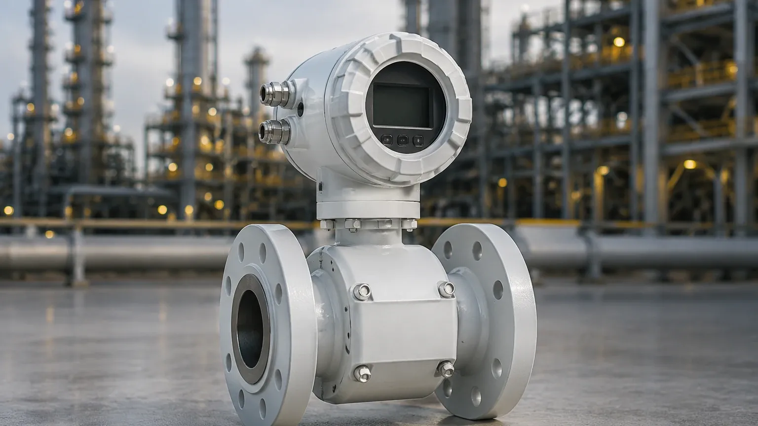
In modern industrial processing, the transition from mechanical to electronic gas flow measurement represents a significant shift toward precision, data integration, and long-term reliability. An electronic gas flow meter is a device that utilizes solid-state sensors and digital electronics to measure the volume or mass of a gas moving through a pipeline. Unlike traditional mechanical meters that rely on moving parts like diaphragms or turbines, electronic versions offer enhanced durability and the ability to communicate directly with building management systems (BMS) or industrial control platforms.
For engineers and facility managers, selecting the correct electronic gas flow meter requires a deep understanding of gas dynamics, sensor physics, and the specific requirements of the application, whether it involves compressed air, natural gas, or specialized process gases like nitrogen or argon. This guide provides a technical overview of current technologies, selection criteria, and installation best practices to ensure accurate measurement in diverse industrial environments.
Measurement Principles of Electronic Gas Flow Meters
Electronic gas flow meters operate on several distinct physical principles. Understanding these is the first step in determining which technology fits a specific process.
Thermal Mass Flow Measurement
Thermal mass flow meters operate based on the principle of heat transfer. The sensor typically consists of two Resistance Temperature Detectors (RTDs). One RTD acts as a reference sensor to measure the ambient temperature of the gas, while the second RTD is heated to a constant temperature differential above the gas temperature. As gas flows past the heated sensor, it carries away heat. The electronic circuit measures the amount of power required to maintain the temperature differential. Since the cooling effect is directly related to the number of gas molecules passing the sensor, the device provides a direct mass flow measurement without needing additional pressure or temperature compensation.
Ultrasonic (Transit-Time) Measurement
Ultrasonic meters use sound waves to determine the velocity of the gas. Two transducers are mounted on the pipe, one upstream and one downstream. They emit ultrasonic pulses to each other. The pulse traveling with the flow moves faster than the pulse traveling against the flow. The difference in transit time is directly proportional to the gas velocity. Electronic processing then calculates the volumetric flow rate. This technology is highly valued for its wide turndown ratio and lack of pressure drop, as there are no obstructions in the flow path.
Vortex Shedding Measurement
Vortex meters utilize the Karman Vortex Street principle. A "bluff body" is placed in the center of the flow stream. As gas flows past this obstruction, vortices (swirls) are shed alternately on each side. The frequency of these vortices is directly proportional to the velocity of the gas. Electronic sensors, often piezoelectric crystals, detect these pressure fluctuations and convert them into a flow signal. This method is robust and suitable for high-velocity gas applications.
Key Evaluation Criteria for Industrial Gas Flow Measurement
When evaluating an electronic gas flow meter, several technical parameters must be confirmed to ensure the device performs within its specified accuracy limits.
1. Gas Composition: Electronic meters, particularly thermal mass types, are calibrated for specific gas mixtures. If the gas composition changes (e.g., a shift in the methane-to-ethane ratio in natural gas), the accuracy of the thermal meter will drift. Ultrasonic and vortex meters are generally less sensitive to composition changes but still require density data for mass flow calculations.
2. Flow Range and Turndown Ratio: The turndown ratio is the ratio between the maximum and minimum measurable flow. For applications like leak detection, a high turndown ratio (e.g., 100:1) is essential. Thermal mass meters excel in low-flow sensitivity, whereas vortex meters may have a "cut-off" below which they cannot detect vortices.
3. Process Conditions: Designers must confirm the maximum operating pressure and temperature. High-pressure applications require specific housing ratings (e.g., ANSI or DIN flanges), while high-temperature gases may require remote-mounted electronics to protect the circuitry from heat damage.
4. Accuracy and Repeatability: It is vital to distinguish between "percentage of reading" and "percentage of full scale." An accuracy of ±1% of reading is significantly more precise at low flow rates than ±1% of full scale.
Technology Comparison and Selection Table
The following table compares the most common electronic gas flow measurement technologies used in industrial automation.
| Feature | Thermal Mass Flow | Ultrasonic (Transit-Time) | Vortex Shedding |
| :— | :— | :— | :— |
| Primary Measurement | Mass Flow | Volumetric Flow | Volumetric Flow |
| Typical Accuracy | ±1% of Reading | ±0.5% to ±1% of Reading | ±1% of Reading |
| Turndown Ratio | Up to 100:1 | Up to 50:1 | 10:1 to 20:1 |
| Pressure Drop | Negligible (Insertion) | Zero | Moderate |
| Moving Parts | None | None | None |
| Key Advantage | No P&T compensation needed | High accuracy, no obstruction | Very stable at high velocity |
| Limitation | Sensitive to moisture | High initial cost | Minimum flow required |
Installation Guidelines and Best Practices
The performance of an electronic gas flow meter is heavily dependent on the installation environment. Even the most sophisticated sensor will provide inaccurate data if the flow profile is disturbed.
Straight Pipe Requirements
Most electronic meters require a "fully developed flow profile" to measure accurately. This usually means a minimum of 10 to 20 diameters (10D to 20D) of straight pipe upstream of the meter and 5 diameters (5D) downstream. If the installation site has elbows, valves, or reducers close to the meter, the resulting turbulence will cause fluctuations in the reading. In tight spaces, flow conditioners (perforated plates or vane-type) may be used to shorten the required straight runs.
Orientation and Moisture Management
For gas applications, meters should ideally be installed in a horizontal pipe. If the gas contains potential moisture or condensate, the sensor should be positioned at the top of the pipe (the 12 o'clock position) to prevent water droplets from collecting on the sensor head. In vertical installations, the flow should generally be upward to ensure that any liquid phase falls away from the sensor by gravity.
Calibration and Power Supply
Electronic meters require stable DC power (typically 24V DC). In hazardous areas, intrinsically safe barriers or explosion-proof housings are mandatory. Furthermore, because electronic sensors can drift over time due to sensor coating or electronic aging, a schedule for field validation or factory recalibration should be established. For more information on maintaining instrumentation and exploring compatible measurement technologies, you may visit the Main Page.
Operational Limitations and Common Risks
While electronic gas flow meters offer superior performance over mechanical types, they are not without limitations. Engineers should be aware of the following risks:
* Moisture and Particulates: In thermal mass meters, water droplets hitting the heated sensor can be interpreted as a massive spike in flow because water carries away much more heat than gas. In such cases, air dryers or moisture separators are required upstream.
* Signal Noise: In ultrasonic meters, high-frequency noise from nearby pressure-reducing valves (PRVs) can interfere with the ultrasonic pulses, leading to signal loss. This is known as "acoustical noise interference."
* Calibration Mismatch: Using a meter calibrated for air to measure Carbon Dioxide (CO2) without adjusting the internal K-factors will result in significant errors, as the thermal properties of the gases differ.
* Low Flow Cut-off: Vortex meters have a minimum Reynolds number required to shed vortices. If the flow drops below this threshold, the meter will read zero, even if some gas is still moving through the pipe.
Integration with Process Control Systems
One of the primary reasons for choosing an electronic gas flow meter is the ease of integration. Most modern units provide multiple output options:
* Analog Outputs: A standard 4-20mA signal represents the flow rate, which can be easily scaled in a PLC (Programmable Logic Controller).
* Pulse Outputs: Used for totalizing the amount of gas consumed over time, where each pulse represents a specific volume (e.g., 1 pulse = 1 m³).
* Digital Communication: Protocols like Modbus RTU, HART, or Profibus allow the meter to transmit not just flow data, but also diagnostic information, gas temperature, and internal sensor health status.
This connectivity allows for advanced strategies like mass balance calculations, where the gas input to a system is compared against the output to detect hidden leaks or process inefficiencies.
Frequently Asked Questions (FAQs)
Q: Does an electronic gas flow meter need to be recalibrated every year?
A: While many manufacturers recommend annual calibration, the actual interval depends on the gas purity and the criticality of the measurement. In clean, dry gas applications, many electronic meters can maintain accuracy for several years. Field validation checks can often extend the time between factory calibrations.
Q: Can I use a thermal mass flow meter for steam?
A: Generally, no. Thermal mass flow meters are designed for gases. Steam is often too hot and contains moisture that would cause erratic readings. Vortex meters are the preferred electronic choice for steam measurement.
Q: What is the difference between "Standard" and "Actual" flow?
A: Actual flow (Am³/h) is the volume of gas at the current operating pressure and temperature. Standard flow (Nm³/h or SCFM) is the volume the gas would occupy at a reference pressure and temperature (e.g., 101.325 kPa and 0°C). Electronic meters can often calculate both, providing a consistent basis for billing and process control.
Q: How do I handle gas flow measurement in explosive environments?
A: You must select a meter with the appropriate hazardous area certifications, such as ATEX, IECEx, or UL/CSA. These meters use explosion-proof enclosures or intrinsically safe electronics to ensure they cannot act as an ignition source.
Conclusion
Selecting an electronic gas flow meter is a critical decision that impacts the efficiency and safety of industrial operations. By understanding the underlying physics—whether thermal, ultrasonic, or vortex—and strictly adhering to installation requirements regarding straight pipe runs and gas composition, engineers can achieve highly accurate and maintenance-free measurement. As industries move toward more data-driven models, the integration capabilities of electronic meters provide the necessary foundation for optimized gas management and energy conservation. For further technical specifications and to Review product options and application support, consulting with a specialized manufacturer is recommended to ensure the selected instrument matches the specific nuances of the process environment.