Ultrasonic Density Meter
Ultrasonic Density Meter
In the landscape of industrial process control, the ability to measure the density of liquids and slurries in real-time is vital for maintaining product quality, optimizing chemical dosing, and ensuring the efficiency of transport systems. The ultrasonic density meter has emerged as a preferred solution for many engineers due to its non-invasive nature and its ability to handle challenging media that might damage or clog traditional intrusive sensors. As a specialized instrument, it complements other measurement technologies such as those found on the Main Page of professional instrumentation providers like Welk.
This guide provides a comprehensive technical overview of ultrasonic density measurement, covering the underlying physics, selection criteria, installation requirements, and practical limitations encountered in industrial environments.
Understanding the Ultrasonic Density Meter
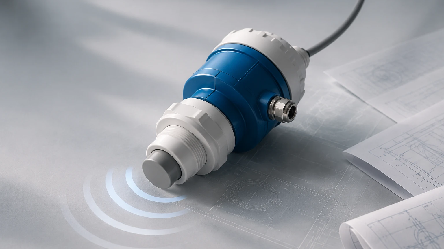
An ultrasonic density meter is an industrial instrument designed to determine the density or percent solids concentration of a fluid by analyzing the behavior of high-frequency sound waves as they pass through the medium. Unlike Coriolis meters, which require the fluid to pass through vibrating tubes, or nuclear density meters, which use radioactive isotopes, ultrasonic meters typically utilize transducers mounted on the exterior of a pipe or integrated into a spool piece.
These devices are particularly prevalent in industries such as mining, wastewater treatment, dredging, and chemical processing. In these sectors, the media often contain abrasive solids or corrosive chemicals that would quickly degrade intrusive sensors. By using ultrasonic energy, operators can achieve continuous, maintenance-free measurement without interrupting the flow or risking leaks.
Measurement Principles and Technology
The operation of an ultrasonic density meter is based on the interaction between acoustic waves and the physical properties of the fluid. There are two primary methods used to derive density from ultrasonic signals: Velocity of Sound (VOS) and Acoustic Attenuation.
1. Velocity of Sound (VOS)
The speed at which sound travels through a liquid is determined by the medium's density ($\rho$) and its bulk modulus ($K$), which represents the fluid's resistance to compression. The relationship is defined by the formula:
$$c = \sqrt{\frac{K}{\rho}}$$
Where:
- $c$ is the speed of sound (m/s).
- $K$ is the bulk modulus (Pa).
- $\rho$ is the density (kg/m³).
In many pure liquids, as the density increases, the speed of sound also changes in a predictable manner. By measuring the time of flight of an ultrasonic pulse across a known distance (the pipe diameter), the meter can calculate the velocity and, subsequently, the density. However, because temperature significantly affects both density and the bulk modulus, high-precision ultrasonic density meters always include an integrated temperature sensor to provide compensation.
2. Acoustic Attenuation
In applications involving slurries or suspended solids, the attenuation of the sound wave—the loss of signal strength—is often a more accurate indicator of density or concentration. As the ultrasonic pulse travels through a slurry, the sound energy is absorbed and scattered by the solid particles.
The degree of attenuation depends on the frequency of the signal, the size of the particles, and the concentration of the solids. By comparing the strength of the transmitted signal to the received signal, the electronic unit can determine the concentration of the suspended material. Modern instruments often combine both VOS and attenuation data to provide a robust measurement that accounts for variations in both the carrier liquid and the solid particles.
Key Evaluation Criteria for Selection
Selecting the right ultrasonic density meter requires a detailed understanding of the process conditions. Engineers should evaluate the following factors before procurement:
Pipe Material and Diameter
Ultrasonic signals must be able to pass through the pipe wall and the fluid. While most instruments work well on carbon steel, stainless steel, and various plastics, pipes with internal liners (such as rubber or glass) can present challenges. The thickness of the liner and whether it is fully bonded to the pipe wall will affect signal transmission. Standard systems typically support pipe diameters ranging from 50 mm to over 1,000 mm.
Fluid Characteristics
The nature of the fluid is the most critical factor. Ultrasonic meters perform best in homogeneous liquids or slurries with consistent particle size distributions. If the fluid contains a high volume of entrained air or gas bubbles, the ultrasonic signal will be scattered, leading to measurement errors or "signal loss" alarms. Similarly, extremely high viscosities can dampen the signal significantly.
Concentration Range
It is essential to define the expected density range. For example, a lime slurry application might require a range of 1,000 to 1,300 kg/m³, while a mining tailings application might reach much higher concentrations. Ensure the instrument's sensitivity is aligned with the required precision over the specific operating range.
Environmental Conditions
Consider the ambient and process temperatures. Standard transducers are often rated up to 80°C or 100°C, but high-temperature versions are available for specialized chemical processes. Additionally, if the installation is outdoors, the electronic transmitter should have an appropriate IP rating (e.g., IP65 or IP67) to protect against moisture and dust.
Comparison with Alternative Technologies
To understand where the ultrasonic density meter fits within a project, it is helpful to compare it against other common density measurement technologies.
| Feature | Ultrasonic Density Meter | Nuclear Density Meter | Coriolis Mass Flow Meter |
| :— | :— | :— | :— |
| Measurement Principle | Acoustic attenuation/velocity | Gamma ray absorption | Oscillating tube (inertia) |
| Installation Type | Non-invasive (Clamp-on/Spool) | Non-invasive (External) | Inline (Intrusive) |
| Regulatory Requirements | None | High (Licensing, Radiation Safety) | None |
| Safety | High (No hazards) | Requires specialized handling | High |
| Maintenance | Low (No moving parts) | Low (But requires periodic leak tests) | Moderate (Potential for wear/clogging) |
| Initial Cost | Moderate | High | High (Especially for large pipes) |
| Abrasive/Corrosive Media | Excellent (No contact) | Excellent (No contact) | Limited (Wear on tubes) |
Installation Guidelines and Best Practices
The accuracy of an ultrasonic density meter is highly dependent on proper installation. Even the most advanced sensor will fail to provide reliable data if it is poorly positioned.
1. Straight Pipe Requirements
To ensure a stable and representative flow profile, the sensors should be installed on a straight section of pipe. The general rule of thumb is to have at least five pipe diameters (5D) of straight run upstream of the sensors and two pipe diameters (2D) downstream. This minimizes turbulence caused by elbows, valves, or pumps.
2. Mounting Orientation
For horizontal pipes, the transducers should never be mounted at the very top or the very bottom. The top of the pipe is where air bubbles collect, and the bottom is where sediment may settle. The ideal position is at the 3 o'clock and 9 o'clock positions (the horizontal centerline).
In many slurry applications, a vertical upward flow is preferred. This ensures that the pipe is always full and that any air bubbles naturally rise and move past the sensors quickly, while solids remain evenly distributed.
3. Coupling and Signal Integrity
For clamp-on ultrasonic density meters, the interface between the transducer and the pipe wall must be airtight. A specialized acoustic couplant (grease or epoxy) is used to eliminate any air gaps. Over time, couplant can dry out in high-temperature environments, so periodic inspection or the use of solid foil couplants is recommended.
4. Zeroing and Calibration
Once installed, the meter must be calibrated. This typically involves:
- Zero Calibration: Filling the pipe with a known reference fluid (usually clean water) and performing a zero-point adjustment.
- Span/Sample Calibration: Taking a physical sample of the process fluid, measuring its density in a laboratory, and entering that value into the meter to adjust the slope of the measurement curve.
Limitations and Operational Challenges
While highly versatile, the ultrasonic density meter is not a universal solution for every application. Engineers must be aware of the following limitations:
* Entrained Air: This is the primary enemy of ultrasonic measurement. Even 1-2% air by volume can completely block the ultrasonic signal. In applications where aeration is likely (e.g., after a centrifugal pump), a de-aeration tank or an air trap should be installed upstream.
* Extremely High Concentrations: There is a physical limit to how much solid material a signal can penetrate. In very thick slurries (typically above 60% solids by weight, depending on the material), the signal may become too weak to provide a reliable reading.
* Particle Size Variations: If the particle size distribution changes drastically during the process, the attenuation characteristics will also change, which may be interpreted by the meter as a change in density. This is particularly relevant in mining applications where ore hardness varies.
* Coating and Scaling: If the interior of the pipe develops a thick layer of scale (e.g., calcium carbonate buildup), the ultrasonic signal will be attenuated by the scale rather than the fluid. Regular cleaning or the use of specialized spool pieces with non-stick liners may be required.
Frequently Asked Questions (FAQ)
Q: Can an ultrasonic density meter measure the density of a gas?
A: Generally, no. These instruments are designed for liquids and liquid-solid slurries. The acoustic impedance of gas is too low for standard industrial ultrasonic density meters to provide accurate results.
Q: How often does the instrument need recalibration?
A: If the process fluid remains consistent in terms of chemical composition and particle size, the meter can remain accurate for years. However, a quarterly check against a laboratory sample is considered best practice in most ISO-certified facilities.
Q: Does the pipe material affect the accuracy?
A: The pipe material affects the signal strength but not necessarily the accuracy, provided the meter is calibrated for that specific pipe. Uniform materials like steel and PVC are ideal. Cast iron can be more difficult due to its porous internal structure, which scatters sound.
Q: Is it possible to measure density in a partially filled pipe?
A: No. The ultrasonic path must be completely submerged in the fluid. If the pipe is not full, the signal will travel through the air space and fail to return a valid density reading. Always install the meter in a location where the pipe remains full under all operating conditions.
Conclusion
The ultrasonic density meter represents a significant advancement in non-contact process instrumentation. By leveraging the principles of acoustic velocity and attenuation, it provides a safe, regulation-free, and low-maintenance alternative to nuclear and intrusive measurement methods. When correctly selected and installed according to the guidelines mentioned above, it serves as a reliable component in any industrial automation system. For those seeking to integrate these sensors into broader level and flow control architectures, reviewing the technical resources and product options available on the Main Page is an essential next step in project planning.