Ultrasonic Flow Sensor Clamp on
Ultrasonic Flow Sensor Clamp on
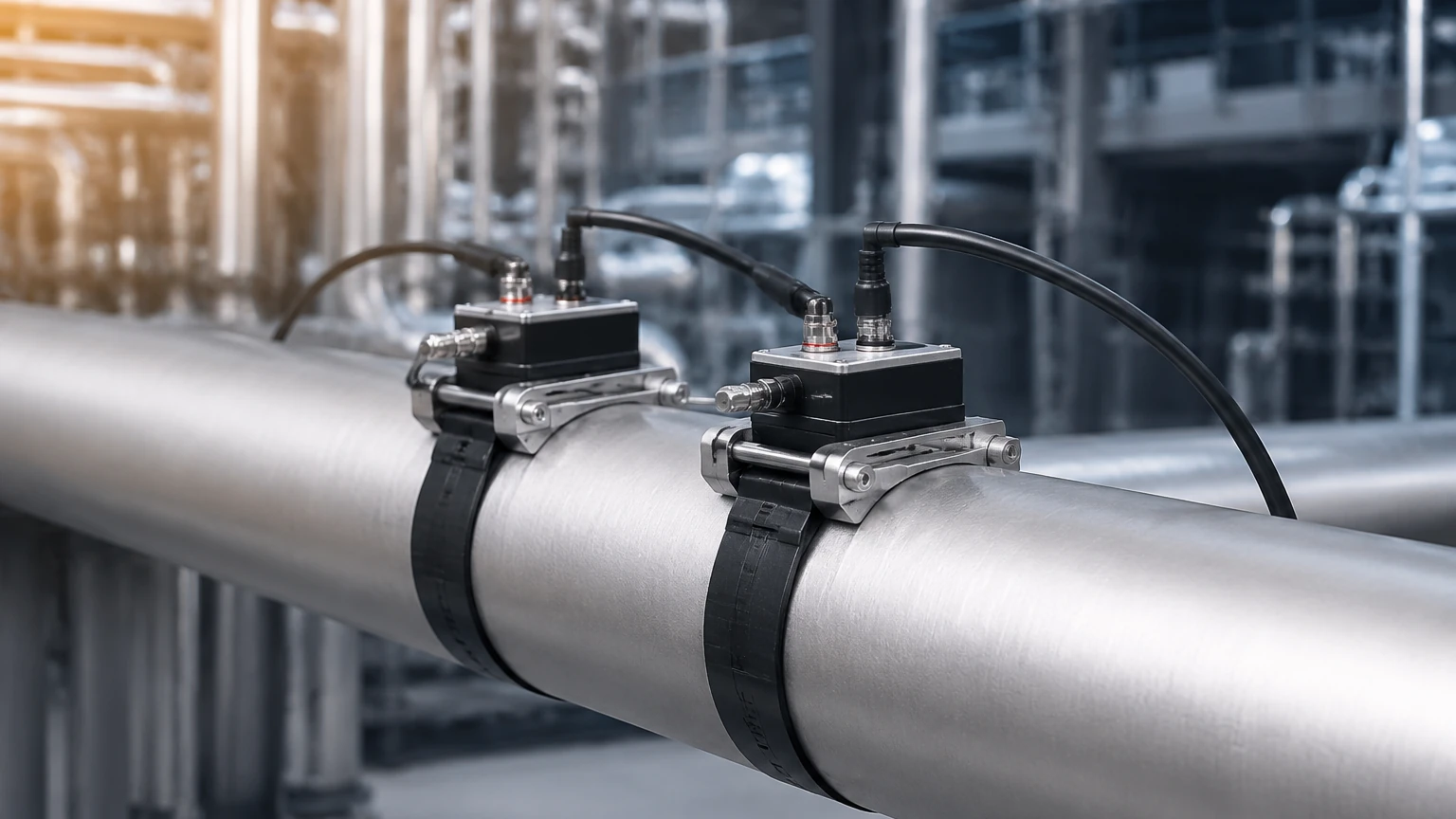
Non-invasive flow measurement has become a cornerstone of modern industrial automation, particularly in sectors where process downtime for installation is not an option. An ultrasonic flow sensor clamp on provides a versatile, accurate, and cost-effective method for measuring the velocity of liquids within a pipe without cutting the line or interrupting the flow. This technology is widely utilized in water treatment, chemical processing, and oil and gas industries to monitor resources and optimize process efficiency.
By utilizing transducers that are strapped to the exterior of a pipe, these sensors eliminate the risks of leakage, pressure drops, and chemical compatibility issues associated with wetted or inline flow meters. Understanding the underlying physics, selection criteria, and installation nuances is essential for engineers seeking to integrate these devices into their process control systems.
Measurement Principles of Ultrasonic Flow Sensors
To effectively implement an ultrasonic flow sensor clamp on, one must first understand the two primary measurement methodologies: Transit-Time and Doppler Effect. Both rely on ultrasonic sound waves—typically in the range of 0.5 MHz to 2 MHz—but they apply different physical principles based on the nature of the fluid.
Transit-Time (Time-of-Flight)
Transit-time measurement is the most common method for clean liquids. It operates on the principle that sound waves traveling in the direction of the flow move faster than waves traveling against it. Two transducers are mounted on the pipe, acting as both transmitters and receivers. They send ultrasonic pulses back and forth through the fluid.
The difference in the time it takes for the signal to travel upstream versus downstream is directly proportional to the velocity of the liquid. The governing equation for flow velocity ($v$) can be simplified as:
$$v = K \cdot \frac{\Delta t}{t_{avg}^2}$$
Where $K$ is a calibration constant, $\Delta t$ is the time difference, and $t_{avg}$ is the average transit time. This method is highly accurate for fluids with less than 2% suspended solids or aeration.
Doppler Effect
The Doppler method is used for "dirty" or aerated liquids. It requires reflectors, such as suspended particles or entrained air bubbles, to function. The sensor transmits a continuous ultrasonic signal into the fluid. When this signal hits a moving particle, it reflects back to the receiver with a frequency shift (the Doppler shift). The magnitude of this shift is proportional to the flow velocity. This technology is ideal for wastewater, slurries, and liquids with significant aeration where transit-time signals would be scattered or absorbed.
Key Evaluation Criteria for Selection
Selecting the correct ultrasonic flow sensor clamp on requires a detailed analysis of the application environment. Unlike inline meters, the performance of a clamp-on sensor is heavily influenced by the pipe material and the fluid's acoustic properties.
Pipe Material and Condition
The ultrasonic signal must pass through the pipe wall, the fluid, and back. Therefore, the pipe material must be a good conductor of sound. Common materials include carbon steel, stainless steel, PVC, and ductile iron. However, pipes with internal liners (such as cement, rubber, or glass) can pose challenges if there is an air gap between the liner and the pipe wall, as air effectively blocks ultrasonic waves.
Fluid Characteristics
For transit-time sensors, the fluid must be relatively clean. If the fluid contains high concentrations of solids (sludge) or gas bubbles, the signal will attenuate, leading to inaccurate readings or total signal loss. Conversely, Doppler sensors require these impurities to function. Temperature also plays a role, as the speed of sound in a liquid changes with temperature; most modern sensors include temperature compensation algorithms to maintain accuracy.
Flow Profile and Reynolds Number
Accuracy is dependent on a fully developed flow profile. The sensor measures the velocity at a specific path, and the meter’s electronics calculate the average volumetric flow based on the pipe's cross-sectional area and the Reynolds number. To ensure a stable profile, the sensor must be placed away from turbulence-inducing components like pumps, valves, and elbows.
Practical Selection Table
The following table provides a quick reference for determining the suitability of ultrasonic clamp-on technology based on common industrial parameters.
| Parameter | Transit-Time Clamp-On | Doppler Clamp-On |
| :— | :— | :— |
| Fluid Type | Clean liquids, water, oils | Slurries, wastewater, aerated liquids |
| Suspended Solids | < 2% by volume | > 100 ppm (minimum size ~100 microns) |
| Pipe Size Range | DN15 to DN6000 (1/2" to 240") | DN25 to DN3000 (1" to 120") |
| Accuracy | ±0.5% to ±2.0% of rate | ±2.0% to ±5.0% of full scale |
| Installation | Non-invasive, no downtime | Non-invasive, no downtime |
| Repeatability | 0.1% to 0.3% | 0.5% to 1.0% |
| Typical Velocity | 0.01 to 12 m/s | 0.05 to 10 m/s |
Installation Considerations and Mounting Methods
The success of an ultrasonic flow sensor clamp on installation depends largely on the physical mounting of the transducers. There are three primary mounting configurations, chosen based on pipe diameter and fluid attenuation.
1. V-Method (Reflective): The most common configuration for pipes ranging from DN25 to DN400. Both transducers are mounted on the same side of the pipe. The signal travels through the fluid, reflects off the opposite wall, and returns to the second transducer. This doubles the path length, increasing the time resolution and accuracy.
2. Z-Method (Direct): Used for larger pipes (typically > DN400) or where the fluid is highly attenuative. Transducers are mounted on opposite sides of the pipe. The signal travels directly across the pipe once. This method provides a stronger signal but a shorter transit time.
3. W-Method: Used for very small pipes (DN15 to DN40). The signal reflects three times within the pipe, creating a very long path length to compensate for the short distance between transducers.
The Role of Acoustic Couplant
Because air is a poor conductor of high-frequency sound, a coupling agent (grease, gel, or silicone) must be applied between the transducer face and the pipe surface. This couplant eliminates the air gap and ensures maximum signal transmission. In permanent installations, high-temperature or long-term stable couplants are required to prevent drying out over time.
Straight Pipe Requirements
To achieve the specified accuracy, the flow must be laminar and stable. Standard engineering guidelines recommend a minimum of 10D upstream (10 times the pipe diameter) and 5D downstream of straight pipe from any disturbance. If a valve or pump is located upstream, this requirement may increase to 20D or 30D.
Limitations and Common Risks
While highly versatile, the ultrasonic flow sensor clamp on is not a universal solution. Engineers should be aware of the following limitations:
* Pipe Wall Scaling: Internal scaling or rusting in older pipes can scatter the ultrasonic signal. In some cases, the pipe must be cleaned externally, or the transducers must be moved to a cleaner section of the line.
* Aeration and Cavitation: If a pump is cavitating or if there is a leak on the suction side, air bubbles will enter the stream. In transit-time meters, this can cause the signal to "drop out."
* Zero-Flow Calibration: For maximum accuracy, the meter should be calibrated at a zero-flow state (valves closed and pipe full). If the system cannot be stopped, the accuracy may be slightly degraded.
* Wall Thickness Measurement: The meter calculates flow based on the internal diameter. If the pipe wall thickness is unknown or incorrectly entered into the transmitter, the resulting flow calculation will be inaccurate. Using an ultrasonic thickness gauge is recommended before installation.
Frequently Asked Questions (FAQs)
Q: Can a clamp-on sensor measure flow in partially filled pipes?
A: No. Standard ultrasonic clamp-on sensors require the pipe to be completely full (100%) to accurately calculate the cross-sectional area and flow velocity. For partially filled pipes, specialized area-velocity sensors or level-based flume measurements are required.
Q: Does the pipe material affect the accuracy?
A: Indirectly, yes. The transmitter must know the speed of sound in the pipe material to calculate the refraction angle of the signal. If the material is unknown or highly non-homogeneous (like some composites), accuracy will suffer.
Q: How often does the couplant need to be replaced?
A: In temporary or portable applications, it is applied every time. For permanent installations, using a high-quality silicone-based couplant and proper tensioning straps can ensure the signal remains stable for several years. If signal strength degrades, the couplant is the first thing to check.
Q: Can it measure gas flow?
A: Most industrial clamp-on units are designed for liquids. While gas clamp-on meters exist, they require much higher-powered transducers and specialized signal processing due to the very low density of gas compared to liquid.
Conclusion
The ultrasonic flow sensor clamp on represents a significant advancement in process monitoring, offering a balance of accuracy and ease of installation that wetted sensors cannot match. By selecting the appropriate measurement principle—transit-time for clean liquids or Doppler for slurries—and adhering to strict installation guidelines regarding pipe straightness and acoustic coupling, industrial operators can achieve reliable flow data with zero process interruption.
For engineers looking to integrate these flow solutions with comprehensive tank and vessel monitoring, exploring advanced level measurement instruments is often the next step. Reliable data from both flow and level sensors ensures total mass balance and process safety. To review a wide range of industrial measurement options and application support, visit the Main Page for technical specifications and customized OEM/ODM services.