Ultrasonic Flow
Ultrasonic Flow
In the landscape of industrial process control, ultrasonic flow measurement has emerged as a cornerstone technology for non-invasive and high-precision monitoring. By utilizing high-frequency sound waves, these systems determine the velocity of fluids within a closed pipe or an open channel without requiring physical contact with the media. This capability is particularly valuable in sectors such as water treatment, chemical processing, and oil and gas, where maintaining the integrity of the piping system and preventing contamination are paramount. As industries move toward more digitized and maintenance-free operations, understanding the mechanics, selection criteria, and installation nuances of ultrasonic flow systems is essential for engineering professionals.
Fundamental Principles of Ultrasonic Flow Measurement
Ultrasonic flow measurement relies on the propagation of acoustic waves through a fluid medium. Unlike mechanical meters that use moving parts like turbines or gears, ultrasonic meters use transducers to send and receive sound pulses. There are two primary methods used to calculate flow: Transit-Time and Doppler Effect.
Transit-Time Principle
The transit-time method is the most common approach for clean liquids. It operates by mounting two transducers on a pipe, either across from each other or on the same side. These transducers act as both transmitters and receivers. One transducer sends an ultrasonic signal downstream (with the flow), while the other sends a signal upstream (against the flow).
Because the sound waves traveling downstream are "pushed" by the fluid velocity, they reach the receiving transducer faster than the waves traveling upstream. The flow meter measures this time difference (delta-t) with extreme precision, often in nanoseconds. The velocity of the fluid ($v$) is proportional to this time difference. Once the velocity is known, and the cross-sectional area of the pipe is programmed into the device, the volumetric flow rate can be calculated.
Doppler Effect Principle
The Doppler effect method is utilized for fluids containing suspended solids, bubbles, or entrained gases. In this scenario, a transducer transmits an ultrasonic signal of a known frequency into the fluid. This signal reflects off the particles or bubbles moving within the stream.
According to the Doppler principle, the frequency of the reflected signal shifts relative to the original frequency based on the velocity of the reflecting objects. By measuring this frequency shift, the meter determines the flow velocity. This method requires a minimum concentration of "reflectors" (typically 100 parts per million of particles larger than 75 microns) to function accurately.
Transit-Time vs. Doppler Technology: A Comparative Analysis
Selecting the correct ultrasonic flow technology depends heavily on the characteristics of the fluid and the specific requirements of the application. The following table provides a comparison of the two technologies.
| Feature | Transit-Time | Doppler Effect |
| :— | :— | :— |
| Fluid Type | Clean liquids (water, oils, chemicals) | "Dirty" liquids (slurries, wastewater, aerated liquids) |
| Particle Concentration | < 2% by volume | > 100 ppm (typically) |
| Accuracy | High (0.5% to 2% of velocity) | Moderate (2% to 5% of full scale) |
| Pipe Sizes | 15 mm to 5,000 mm (0.5" to 200") | 25 mm to 5,000 mm (1" to 200") |
| Installation | Inline or Clamp-on | Primarily Clamp-on |
| Typical Applications | Potable water, HVAC, pure chemicals | Sewage, mining slurries, crude oil with gas |
Key Selection Criteria for Industrial Applications
When evaluating ultrasonic flow solutions, engineers must look beyond the basic measurement principle and consider the environmental and physical constraints of the site. For those seeking specialized hardware for level and flow integration, reviewing the Main Page of a dedicated manufacturer can provide specific technical data sheets for various industrial environments.
1. Pipe Material and Liner
Ultrasonic waves must pass through the pipe wall to reach the fluid. Materials like carbon steel, stainless steel, and PVC are excellent conductors. However, pipes with thick liners (such as rubber or cement) or those made of porous materials like cast iron can attenuate the signal. It is critical to confirm the pipe wall thickness and liner material before selection.
2. Fluid Properties
In addition to the presence of solids, the temperature and viscosity of the fluid affect the speed of sound. Most modern ultrasonic flow meters include a library of fluid types (water, glycol, alcohol, etc.) to automatically compensate for these variables. For high-temperature applications exceeding 150°C (302°F), specialized high-temperature transducers and mounting hardware are required.
3. Accuracy and Repeatability Requirements
For billing or custody transfer applications, high-accuracy transit-time meters with multiple paths (multiple pairs of transducers) are often required to account for flow profile irregularities. For simple process monitoring or leak detection, a single-path clamp-on meter may suffice.
Installation Requirements and Best Practices
The accuracy of an ultrasonic flow meter is highly dependent on how and where the transducers are installed. Unlike many other instruments, the "plug-and-play" nature of ultrasonic devices is only effective if the hydraulic conditions are optimized.
Straight Pipe Runs
To ensure a stable and predictable flow profile, the meter must be installed in a section of straight pipe away from disturbances such as pumps, valves, elbows, or reducers. The standard industry guideline is the "10D/5D" rule: the meter should have at least 10 pipe diameters of straight run upstream and 5 pipe diameters downstream. For example, in a 100 mm (4-inch) pipe, there should be 1,000 mm (40 inches) of straight pipe before the meter.
Transducer Mounting Methods
There are three common mounting configurations for clamp-on transducers:
1. V-Method: The signal bounces off the opposite pipe wall once. This is the standard for pipe sizes between 25 mm and 400 mm (1" to 16").
2. Z-Method: Transducers are placed on opposite sides of the pipe, and the signal passes through the fluid once. This is used for large pipes or where the fluid is highly attenuative.
3. W-Method: The signal bounces three times. This is used for very small pipes (under 50 mm or 2") to increase the signal path length and improve resolution.
Acoustic Coupling
For clamp-on meters, there must be no air gap between the transducer face and the pipe surface. A coupling compound (grease or gel) is applied to the transducers. In permanent installations, solid epoxy or stainless steel foil may be used to ensure long-term signal integrity.
Ultrasonic Flow in Open Channels and Level Integration
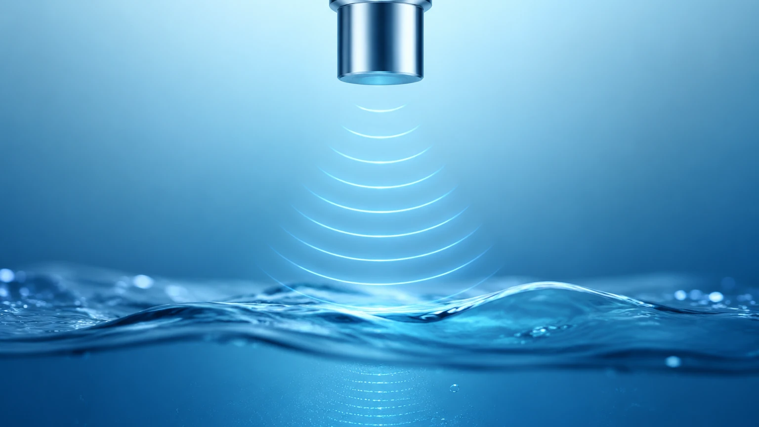
Ultrasonic technology is not limited to closed pipes. In wastewater treatment and irrigation, ultrasonic level sensors are frequently used to measure flow in open channels, such as flumes and weirs. This application bridges the gap between level measurement and flow calculation.
In an open channel, the flow rate is a function of the liquid level (head) behind a primary device (the flume or weir). An ultrasonic level transmitter is mounted above the channel, measuring the distance to the water surface. The internal electronics of the transmitter use programmed formulas (like the Manning equation or specific flume discharge curves) to convert the level measurement into a volumetric flow rate. This method is highly effective because it remains non-contact, preventing the sensor from being fouled by debris or corrosive chemicals in the wastewater.
Technical Limitations and Environmental Considerations
While highly versatile, ultrasonic flow systems have specific limitations that must be addressed during the engineering phase:
* Signal Attenuation: High concentrations of bubbles or solids can scatter the ultrasonic signal in transit-time meters, leading to signal loss. If the fluid is too aerated, a Doppler meter or an alternative technology like electromagnetic flow measurement may be necessary.
* Pipe Condition: Excessive scale buildup or internal corrosion can interfere with the signal path. In some cases, the pipe must be cleaned or a section replaced with an inline spool piece to ensure reliable measurement.
* Ambient Noise: High-frequency vibration from nearby machinery or heavy pumps can sometimes interfere with the ultrasonic signal. Shielded cabling and proper grounding are essential in industrial environments.
* Full Pipe Requirement: For closed-pipe measurement, the pipe must be completely full of liquid. If the pipe is partially full, the meter will either provide an error or a highly inaccurate reading. For partially full pipes, specialized area-velocity flow meters are required.
Frequently Asked Questions (FAQs)
Q: Can ultrasonic flow meters measure gas flow?
A: Yes, but gas applications require specialized high-power transducers because gases are much less dense than liquids, making it harder for sound waves to propagate. Most standard industrial ultrasonic meters are designed for liquids.
Q: How often does the coupling grease need to be replaced?
A: In a well-installed permanent application, coupling grease can last for several years. However, if the signal strength degrades, it is the first thing that should be checked. For extreme environments, mechanical clamping systems with foil interfaces are preferred.
Q: Is it possible to use clamp-on meters on old, corroded pipes?
A: It is possible, but difficult. The exterior of the pipe must be sanded down to bare metal to ensure a smooth contact surface. If the internal corrosion is severe, the signal may be too scattered to provide a reliable reading.
Q: What is the minimum flow velocity required?
A: Most ultrasonic flow meters can measure velocities as low as 0.01 m/s (0.03 ft/s), making them excellent for leak detection and low-flow monitoring.
By adhering to these technical guidelines and understanding the underlying physics of ultrasonic flow, organizations can implement measurement solutions that offer long-term reliability and low total cost of ownership. For more detailed product specifications and to explore level measurement options that complement flow systems, visit the Main Page for professional assistance.