Ultrasonic Meter for Gas
Ultrasonic Meter for Gas
In the landscape of modern industrial automation, the ultrasonic meter for gas has emerged as a critical instrument for both flow measurement and level detection. Unlike traditional mechanical meters that rely on moving parts—which are prone to wear, pressure drops, and mechanical failure—ultrasonic technology utilizes acoustic waves to provide non-intrusive, highly accurate data. For process engineers and facility managers in the chemical, oil and gas, and water treatment sectors, understanding the nuances of how these meters interact with various gas compositions is essential for maintaining operational efficiency and safety.
This article examines the underlying measurement principles of ultrasonic technology in gas applications, provides a framework for selection, and outlines the practical installation considerations necessary for reliable performance.
Measurement Principles of Ultrasonic Gas Instrumentation
Ultrasonic meters operating in gas environments generally fall into two categories: transit-time flow meters and pulse-echo level sensors. Both rely on the propagation of high-frequency sound waves (typically above 20 kHz), but their application of the physics differs significantly.
Transit-Time Principle (Flow Measurement)
For gas flow measurement, the transit-time principle is the industry standard. This method employs pairs of ultrasonic transducers mounted on opposite sides of a pipe. One transducer acts as a transmitter while the other acts as a receiver. The meter measures the time it takes for an ultrasonic pulse to travel across the pipe in two directions: with the flow (downstream) and against the flow (upstream).
Because the gas flow carries the sound waves, the pulse traveling downstream moves faster than the pulse traveling upstream. The difference in these transit times ($Δt$) is directly proportional to the velocity of the gas. By integrating this velocity with the cross-sectional area of the pipe, the meter calculates the volumetric flow rate. Modern electronics within the Main Page of these devices allow for real-time compensation for changes in gas density and temperature.
Pulse-Echo Principle (Level Measurement)
In level measurement applications, an ultrasonic meter for gas (specifically a level transmitter) is mounted at the top of a tank or silo. The transducer emits a pulse that travels through the gas space, hits the surface of the medium (liquid or solid), and reflects back to the sensor.
The distance ($d$) is calculated using the formula:
$$d = \frac{c \times t}{2}$$
Where $c$ is the speed of sound in the specific gas and $t$ is the time of flight. Because the speed of sound varies significantly based on the gas composition and temperature, high-quality instruments include integrated temperature sensors to adjust the calculation dynamically.
Key Evaluation Criteria for Industrial Applications
Selecting the correct ultrasonic meter for gas requires a detailed analysis of the process environment. Engineers must confirm several technical parameters before finalizing a specification.
Gas Composition and Attenuation
Sound travels differently through different gases. For example, the speed of sound in methane is approximately 430 m/s at 20°C, whereas in carbon dioxide, it is roughly 260 m/s. Furthermore, certain gases, such as CO2, exhibit high acoustic absorption (attenuation) at specific frequencies. If the gas mixture in a tank or pipe changes frequently, the meter must be capable of recalibrating its sound-speed profile or use a reference target to maintain accuracy.
Pressure and Temperature Ranges
Ultrasonic transducers for gas must be robust enough to handle process pressures. While ultrasonic level sensors often operate near atmospheric pressure, flow meters in the oil and gas industry may face pressures exceeding 100 bar (10 MPa). High pressure increases the density of the gas, which actually improves the coupling of the acoustic signal between the transducer and the medium. Conversely, in vacuum or very low-pressure environments, ultrasonic signals may fail to propagate entirely.
Accuracy and Turndown Ratio
In B2B procurement, the "turndown ratio" (the ratio of maximum to minimum measurable flow) is a vital metric. Ultrasonic meters for gas often offer ratios of 100:1 or higher, far exceeding the capabilities of orifice plates or turbine meters. This allows a single meter to accurately measure both peak demand and low-leakage rates.
Selection Table: Ultrasonic Meter Specifications
The following table provides a comparison of typical specifications for ultrasonic gas instruments used in industrial automation.
| Feature | Ultrasonic Gas Flow Meter | Ultrasonic Gas Level Sensor |
| :— | :— | :— |
| Primary Function | Measuring gas velocity/volume | Measuring distance to surface |
| Typical Accuracy | ±0.5% to ±1.0% of reading | ±0.25% of measurement range |
| Operating Pressure | Up to 150 bar (15 MPa) | Typically < 3 bar (0.3 MPa) |
| Temperature Range | -200°C to +250°C | -40°C to +95°C |
| Pipe/Range Size | 25 mm to 1000+ mm | 0.2 m to 30 m range |
| Common Media | Natural gas, Nitrogen, Steam | Chemicals, Water, Wastewater |
| Signal Output | 4-20mA, Modbus, HART | 4-20mA, RS485, HART |
Installation Considerations and Best Practices
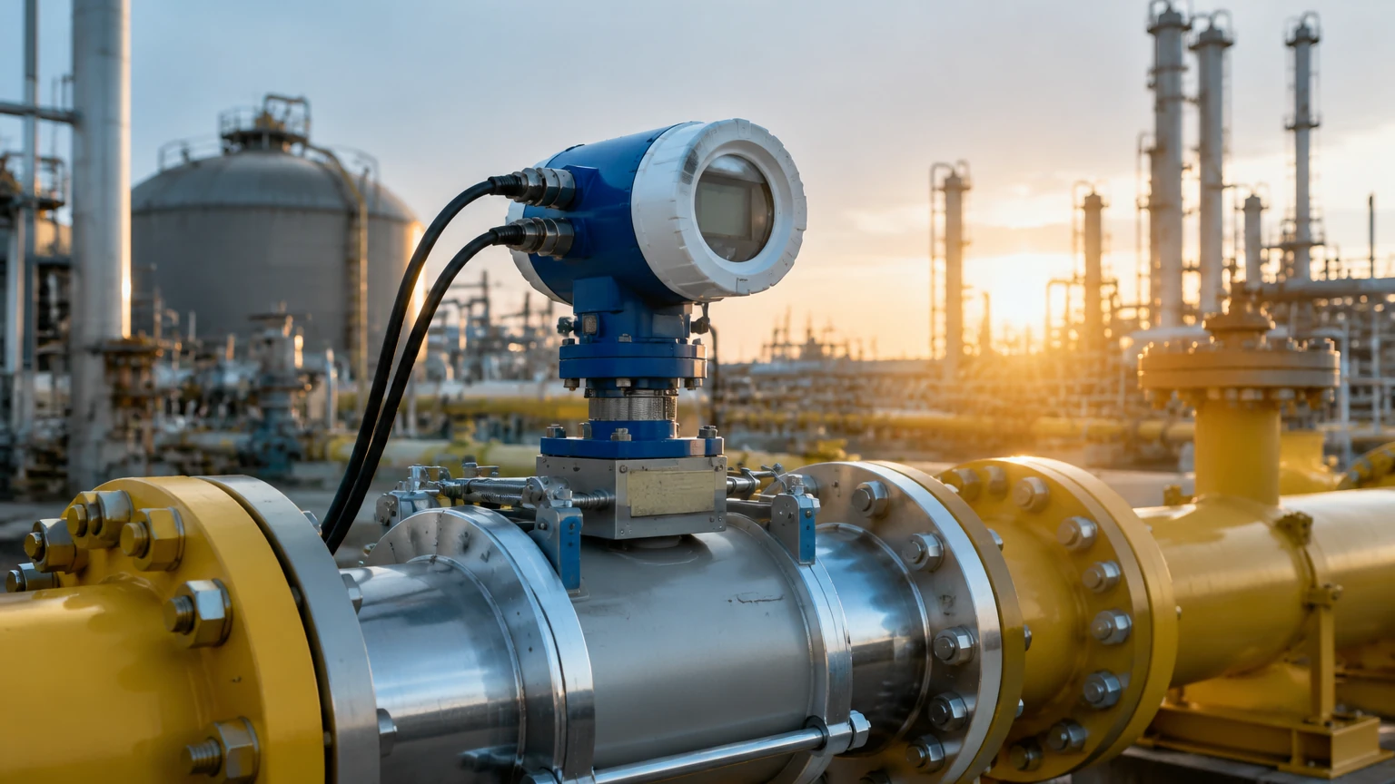
To achieve the theoretical accuracy of an ultrasonic meter for gas, strict adherence to installation guidelines is required. Failure to account for the physical environment often leads to signal "noise" or inaccurate readings.
Straight Pipe Requirements (Flow)
Ultrasonic flow meters are sensitive to turbulence. To ensure a fully developed flow profile, manufacturers typically require a minimum of 10 diameters (10D) of straight, unobstructed pipe upstream of the meter and 5 diameters (5D) downstream. If space is limited, flow conditioners may be installed to reduce swirl and turbulence.
Transducer Mounting and Alignment
For level measurement, the sensor must be mounted perpendicular to the target surface. In gas-filled tanks, avoid mounting the sensor near the fill inlet, as the falling material or gas turbulence can scatter the acoustic signal. Additionally, be aware of the "Dead Zone" (or blocking distance)—the area immediately below the transducer where measurements cannot be taken due to the time required for the transducer to stop vibrating and start listening.
Mitigating Acoustic Noise
Industrial environments are often filled with ultrasonic noise from pressure-reducing valves or heavy machinery. Higher-end ultrasonic meters use advanced digital signal processing (DSP) to filter out these parasitic frequencies, ensuring that only the relevant pulse-echo or transit-time signal is processed.
Limitations and Common Risks
While highly versatile, the ultrasonic meter for gas is not a universal solution for every application. Engineers should be aware of the following limitations:
1. Vacuum Conditions: Ultrasonic waves require a medium to travel. In a total vacuum, the meter will not function. Even in partial vacuums, signal strength is significantly diminished.
2. High Carbon Dioxide Concentrations: CO2 is a known absorber of ultrasonic energy at common industrial frequencies (40-60 kHz). For applications involving high CO2 levels, lower-frequency transducers (around 20-30 kHz) are often required to penetrate the gas.
3. Heavy Foam or Turbulence: In level measurement, thick foam on a liquid surface can absorb the ultrasonic pulse rather than reflecting it, leading to a "loss of echo" error. In such cases, radar level meters may be a more appropriate alternative.
4. Temperature Gradients: Rapid changes in temperature within the gas space can create "layering," which refracts the sound waves and causes measurement errors. Ensuring the gas space is relatively homogenous is key to accuracy.
Frequently Asked Questions (FAQs)
Q: Can an ultrasonic meter for gas measure steam?
A: Yes, specialized high-temperature ultrasonic flow meters are designed for saturated and superheated steam. However, the transducers must be rated for the high temperatures and potential for condensate (slugging) in the line.
Q: How often do these meters require calibration?
A: Because there are no moving parts to wear down, ultrasonic meters are exceptionally stable. In many non-custody transfer applications, a health check every 2-3 years is sufficient. For custody transfer of natural gas, local regulations may require more frequent verification.
Q: Does the pipe material affect the measurement?
A: For inline flow meters, the pipe material is irrelevant as the transducers are in contact with the gas or mounted in a spool piece. For clamp-on ultrasonic meters (which are more common for liquids), the pipe material and wall thickness are critical, though clamp-on gas meters are less common due to the high acoustic impedance mismatch between the pipe wall and the gas.
Q: What is the impact of moisture in the gas?
A: Minor moisture or humidity usually does not affect the meter, provided it does not condense on the transducer face. Heavy condensation can attenuate the signal, requiring transducers with self-cleaning or hydrophobic coatings.
Conclusion
The implementation of an ultrasonic meter for gas offers industrial facilities a path toward higher precision and lower maintenance costs. By understanding the physics of sound propagation in different gas media and adhering to rigorous installation standards, operators can ensure reliable data for process control and billing. When evaluating options, it is recommended to consult with a professional manufacturer like Welk to match the specific transducer frequency and material to your process conditions. For more detailed technical specifications on radar and ultrasonic solutions, visit the Main Page to review product options and application support.