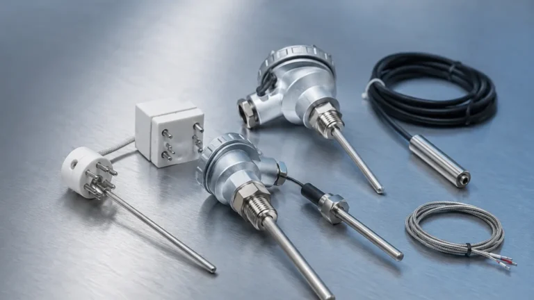
Ultrasonic Transducer Transmitter
Ultrasonic Transducer Transmitter
In the landscape of industrial automation and process control, the ultrasonic transducer transmitter stands as a cornerstone technology for non-contact level measurement. By utilizing high-frequency sound waves to determine the distance to a liquid or solid surface, these instruments provide a reliable, low-maintenance solution for monitoring inventory, managing pump stations, and ensuring safety in chemical storage. This guide provides a comprehensive technical overview of ultrasonic measurement principles, selection criteria, and installation best practices for engineering professionals.
Understanding the Measurement Principle
The operation of an ultrasonic transducer transmitter is based on the "Time of Flight" (ToF) principle. The device contains a piezoelectric crystal that serves as both a transmitter and a receiver. When excited by an electrical pulse, the crystal vibrates at a specific frequency, typically ranging from 20 kHz to over 70 kHz, emitting a burst of ultrasonic energy.
The Pulse-Echo Cycle
1. Emission: The transducer sends out a sound wave pulse toward the target medium.
2. Propagation: The sound wave travels through the air (or gas) at a speed determined by the medium's temperature and composition.
3. Reflection: Upon hitting the surface of the material, the sound wave is reflected back toward the sensor.
4. Reception: The transducer detects the returning echo and converts the mechanical vibration back into an electrical signal.
5. Calculation: The integrated transmitter electronics calculate the distance ($D$) using the formula:
$$D = \frac{c \times t}{2}$$
Where $c$ is the speed of sound and $t$ is the elapsed time between emission and reception.
By subtracting this distance from the known height of the tank (the "Tank Empty" distance), the transmitter determines the actual level of the material. Modern instruments incorporate sophisticated Digital Signal Processing (DSP) to filter out "false echoes" caused by internal tank obstructions like ladders, agitators, or weld seams.
The Relationship Between Transducer and Transmitter
While the terms are often used interchangeably, in a technical context, they refer to distinct components of the measurement system.
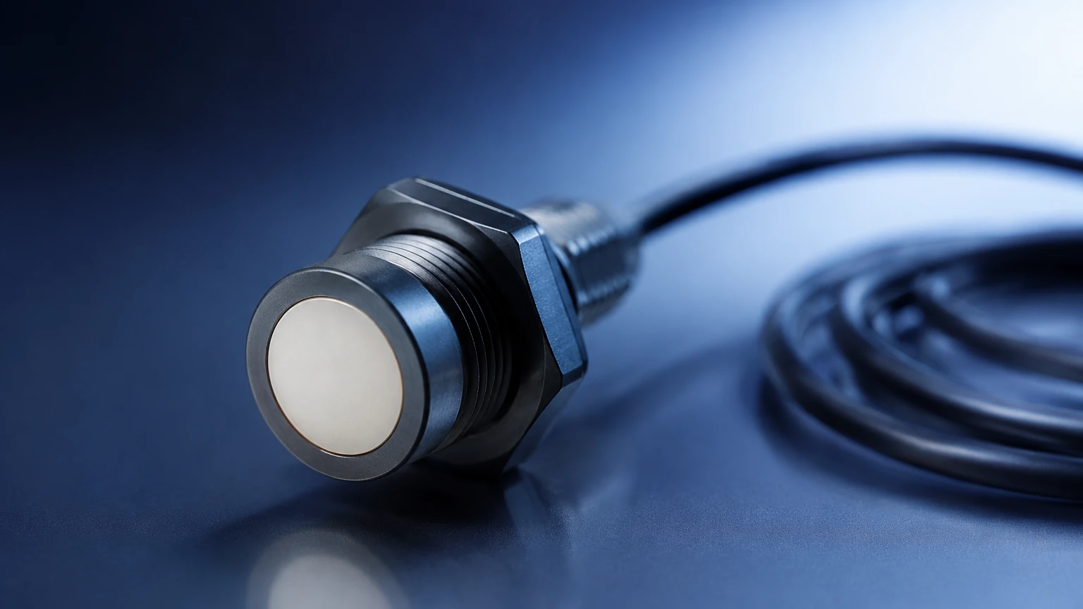
* The Ultrasonic Transducer: This is the physical sensing element. It is responsible for the energy conversion (electrical to mechanical and vice versa). Its design determines the beam angle, the operating frequency, and the chemical resistance of the sensing face.
* The Ultrasonic Transmitter: This refers to the electronics package that powers the transducer, processes the returned signals, performs temperature compensation, and provides an output signal. Common outputs include 4-20mA analog loops, Modbus RTU, or HART protocols.
In many industrial applications, these are housed in a single "compact" unit. However, for high-temperature environments or areas with high vibration, a "remote" configuration is used, where the transducer is mounted at the process point and the transmitter is located in a more accessible, stable environment.
Key Evaluation Criteria for Selection
Choosing the correct ultrasonic transducer transmitter requires a thorough analysis of the process environment. Engineers must balance accuracy requirements against physical constraints. For those evaluating specific models for their facility, the Main Page of industrial equipment providers offers detailed technical specifications for various industrial grades.
1. Measurement Range and Frequency
The frequency of the transducer is inversely proportional to its range.
* High-Frequency (60-80 kHz): Used for short ranges (typically up to 5 meters). These offer higher precision and smaller "dead zones" (the minimum distance required between the sensor and the material).
* Low-Frequency (20-40 kHz): Used for long ranges (up to 30 or 40 meters). Lower frequencies penetrate dust and steam more effectively but require larger transducers and have wider beam angles.
2. Beam Angle and Tank Geometry
The beam angle is the conical area where the ultrasonic energy is concentrated. A narrow beam angle (e.g., 5° to 10°) is preferable because it minimizes the risk of the sound wave hitting the tank walls or internal structures, which can cause interference.
3. Temperature and Pressure
The speed of sound varies with temperature (approximately 0.17% per degree Celsius). Therefore, an integrated temperature sensor is essential for accurate measurement. Most ultrasonic transmitters are limited to atmospheric pressure or slight overpressure, as high pressure significantly alters the density of the air, affecting sound propagation.
4. Chemical Compatibility
The wetted parts of the transducer—usually the face—must be compatible with the process media. Common materials include PVDF (Polyvinylidene fluoride) for corrosive acids or PTFE (Teflon) for high-purity applications.
Practical Selection Table
| Feature | Short-Range Applications | Long-Range / Bulk Solids |
| :— | :— | :— |
| Typical Range | 0.25 m to 6 m | 1 m to 30 m |
| Operating Frequency | 50 kHz – 75 kHz | 20 kHz – 40 kHz |
| Beam Angle | 5° – 8° | 10° – 12° |
| Dead Zone | 0.2 m – 0.3 m | 0.5 m – 1.0 m |
| Common Media | Clean liquids, water, oils | Slurries, wastewater, grains |
| Accuracy | ±0.25% of range | ±0.5% of range |
Installation Best Practices
Proper installation is the most critical factor in the performance of an ultrasonic transducer transmitter. Even the most advanced sensor will fail if mounted incorrectly.
Avoiding the Dead Zone (Blocking Distance)
Every ultrasonic sensor has a "dead zone" immediately below the transducer face where it cannot measure. If the liquid level rises into this zone, the transmitter will report an error or a fixed, incorrect value. Always mount the sensor high enough so that the maximum liquid level never enters the dead zone.
Positioning and Alignment
* Perpendicularity: The transducer face must be perfectly parallel to the surface of the liquid. A tilt of even a few degrees can cause the echo to reflect away from the sensor rather than back to it.
* Distance from Walls: As a general rule, the sensor should be mounted at a distance from the tank wall equal to at least 1/10th of the tank height to avoid side-wall reflections.
* Inflow Avoidance: Never mount the sensor directly above the fill stream. The turbulence and the falling liquid will scatter the ultrasonic signal.
Standpipe Usage
In tanks with heavy foam or extreme turbulence, a stilling well or standpipe can be used. This pipe acts as a guide for the sound wave, providing a smooth surface for measurement. However, the pipe must be smooth on the inside and have a vent hole at the top to equalize pressure.
Limitations and Environmental Factors
While versatile, ultrasonic technology is not a universal solution. Engineers must be aware of the following limitations:
1. Vacuum Conditions: Sound waves require a medium (air or gas) to travel. Ultrasonic transmitters cannot function in a vacuum.
2. Heavy Foam: Dense foam acts as an acoustic absorber, soaking up the sound energy and preventing an echo from returning. In such cases, radar level meters are often a better alternative.
3. Vapor and Gas Layers: If the tank contains heavy vapors or gas layers (like Carbon Dioxide) that vary in density, the speed of sound will change unpredictably, leading to significant measurement errors unless the gas composition is constant and the unit is calibrated for it.
4. Extreme Dust: While low-frequency units can handle some dust, extremely heavy dust during pneumatic filling of silos can attenuate the signal.
Frequently Asked Questions (FAQ)
Q: Can I use an ultrasonic transmitter to measure the level of solids?
A: Yes, but with caveats. Solids like grain or plastic pellets do not form a flat surface; they form a cone (angle of repose). This scatters the signal. Generally, you must use a lower-frequency transducer with a higher power output and a swiveling mounting bracket to aim the sensor correctly.
Q: How does humidity affect the measurement?
A: High humidity increases the density of the air, which slightly increases the speed of sound. For most industrial applications, the error is negligible (less than 0.5%), but for high-precision requirements, it should be noted.
Q: What is the difference between a 2-wire and 4-wire transmitter?
A: A 2-wire transmitter is loop-powered, meaning the power and the 4-20mA signal share the same pair of wires. A 4-wire transmitter has separate wires for power (often 110/220V AC or 24V DC) and the signal output, allowing for higher power consumption which is often needed for long-range transducers.
Conclusion and Next Steps
The ultrasonic transducer transmitter remains one of the most cost-effective and reliable methods for level monitoring across the water treatment, chemical, and food industries. By understanding the physics of sound and adhering to strict installation guidelines, facilities can achieve high-accuracy data with minimal maintenance requirements.
When specifying a system, always confirm the chemical compatibility of the transducer face and ensure the chosen frequency aligns with your required measurement range. For technical support and to explore a wide range of industrial-grade measurement solutions, including radar and ultrasonic options, you may Review product options and application support to find the configuration that best fits your specific process needs.