Vega.am
Vega.am
In the field of industrial process automation, selecting the right level measurement technology is a critical decision that impacts safety, efficiency, and cost-effectiveness. Engineering portals and technical domains such as vega.am serve as essential touchpoints for professionals seeking sophisticated instrumentation solutions. Whether managing water treatment facilities, chemical processing plants, or oil and gas storage, understanding the underlying principles of level sensors is the first step toward successful implementation. This guide provides a comprehensive technical overview of modern level measurement technologies, selection criteria, and practical installation guidance for engineering teams.
Measurement Principles: Radar, Ultrasonic, and Hydrostatic
Before selecting a specific instrument through a platform like vega.am, it is vital to understand the physics governing different measurement methods. Each technology interacts with the process media and environment in unique ways.
Radar Level Measurement (ToF)
Radar sensors operate on the Time-of-Flight (ToF) principle. The device emits high-frequency electromagnetic pulses (typically in the 26 GHz or 80 GHz range) toward the medium. These pulses are reflected by the surface of the product and received by the antenna. The distance is calculated based on the time interval between transmission and reception.
Modern 80 GHz radar technology offers a narrower beam angle, which is particularly beneficial in narrow tanks or vessels with internal obstructions like agitators or heating coils. Because radar waves do not require a medium for propagation, they are largely unaffected by vacuum, high pressure, or temperature fluctuations. However, the dielectric constant (εr) of the medium is a critical factor; materials with low dielectric constants reflect less energy, requiring more sensitive electronics or guided wave radar (GWR) configurations.
Ultrasonic Level Sensors
Ultrasonic sensors also use the ToF principle but rely on mechanical sound waves rather than electromagnetic waves. The sensor emits an ultrasonic pulse that travels through the air, reflects off the liquid or solid surface, and returns to the transducer.
Ultrasonic measurement is a cost-effective, non-contact solution ideal for water and wastewater applications. However, because sound speed is dependent on air density and temperature, these sensors require integrated temperature compensation. They are also sensitive to heavy foam, dust, and significant vapor layers, which can attenuate or scatter the sound waves.
Hydrostatic Level Transmitters
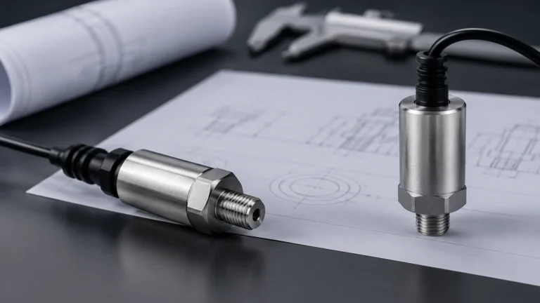
Hydrostatic measurement is a contact-based method that determines the level by measuring the pressure exerted by a liquid column. The principle is based on the formula: *P = ρ × g × h*, where *P* is pressure, *ρ* is the density of the liquid, *g* is gravity, and *h* is the height of the liquid.
This technology is highly reliable for vented tanks or deep wells. In pressurized vessels, a differential pressure (DP) approach is required to subtract the top-side gas pressure from the total pressure at the bottom. Hydrostatic sensors are valued for their robustness and ease of maintenance, though changes in media density must be accounted for to maintain accuracy.
Technical Evaluation Criteria for Process Automation
When evaluating instruments found on vega.am or similar technical repositories, engineers must move beyond basic price comparisons and focus on the technical compatibility of the sensor with the process environment.
1. Media Characteristics: Is the substance corrosive, abrasive, or viscous? For corrosive chemicals, non-contact radar or PTFE-coated hydrostatic probes are preferred. For solids, the angle of repose and dust generation must be considered.
2. Process Conditions: What are the maximum and minimum operating temperatures and pressures? Standard ultrasonic sensors may fail above 80 °C or in pressurized environments, whereas specialized radar units can handle over 200 °C and high-pressure ratings exceeding 40 bar.
3. Accuracy and Repeatability: In custody transfer applications, millimetric accuracy (±1 mm or ±2 mm) is required. For simple pump control in a sump, a lower accuracy of ±10 mm may be sufficient.
4. Output and Integration: Modern industrial environments require digital integration. Common outputs include 4-20 mA with HART, Modbus RTU, or Profibus. Ensuring the sensor matches the existing PLC or SCADA architecture is essential.
Selection Matrix for Industrial Level Sensors
The following table provides a generalized comparison to assist in the initial technology screening process.
| Feature | Radar (Non-Contact) | Ultrasonic | Hydrostatic | Magnetic Level Gauge |
| :— | :— | :— | :— | :— |
| Measurement Range | Up to 120m | Up to 15m | Up to 200m | Up to 6m |
| Accuracy | High (±1mm to ±5mm) | Moderate (±0.25% of range) | High (±0.1% to ±0.5%) | Moderate |
| Pressure Limits | High (Up to 160 bar) | Low (Atmospheric) | High (Varies by flange) | High |
| Temperature Limits | -196 °C to +450 °C | -40 °C to +80 °C | -40 °C to +100 °C | Up to +400 °C |
| Effect of Foam | Minimal (80 GHz) | Significant | None | None |
| Best Use Case | Chemical reactors, silos | Water tanks, sumps | Deep wells, fuel tanks | Visual bypass monitoring |
Engineering Considerations for Installation and Mounting
Correct installation is as important as selecting the right technology. Even the highest-quality sensor found on vega.am will provide inaccurate data if mounted incorrectly.
Radar and Ultrasonic Mounting
* Nozzle Geometry: The mounting nozzle should be as short as possible. If the nozzle is too long or narrow, it can create "ringing" or false reflections that interfere with the actual level signal.
* Obstruction Avoidance: Sensors should be placed away from the tank wall (typically at least 200 mm) and away from inflow streams to prevent turbulence-related errors.
* Beam Path: Ensure the signal path is clear of ladders, agitators, or support struts. If obstructions are unavoidable, many modern sensors offer "false signal suppression" software to map out and ignore these static reflections.
Hydrostatic and Pressure Mounting
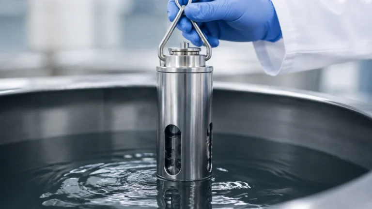
* Positioning: Submersible hydrostatic sensors should be lowered to the lowest point of the tank but kept slightly above the bottom to avoid silt or sludge buildup covering the diaphragm.
* Atmospheric Venting: The capillary tube in the cable of a submersible sensor must remain open to the atmosphere to compensate for changes in barometric pressure. Using a moisture-blocked vent box is recommended for outdoor installations.

Identifying Risks and Limitations in Harsh Environments
Industrial environments present several challenges that can compromise measurement integrity. Recognizing these risks early allows for the implementation of protective measures.
* Signal Attenuation: In ultrasonic systems, heavy steam or a vacuum will prevent the sound wave from traveling. In radar systems, extremely low dielectric liquids (like certain liquefied gases) may result in a signal so weak it is lost in the background noise.
* Build-up and Coating: Sticky or crystallizing media can coat the sensor face or diaphragm. While radar is somewhat resistant to build-up, excessive coating will eventually cause a "high level" false reading. Using a sensor with a flushing connection or a self-cleaning PTFE face can mitigate this.
* Turbulence and Surface Agitation: Rapidly mixing liquids create an uneven surface. For radar, this scatters the signal. Using a stilling well (a bypass pipe) can provide a calm surface for the sensor to measure, ensuring a stable output.
Pre-Selection Checklist for Procurement Teams
Before finalizing an order based on documentation from vega.am or other manufacturers, technical teams should confirm the following details to ensure the hardware is fit-for-purpose:
1. Tank Drawings: Review the internal structure of the vessel to identify potential signal interference.
2. Material Safety Data Sheets (MSDS): Confirm the chemical compatibility of the sensor's wetted parts (e.g., 316L Stainless Steel, Hastelloy, or PVDF) with the process media.
3. Hazardous Area Certification: Determine if the installation site requires ATEX, IECEx, or SIL2/3 functional safety ratings.
4. Power Supply Availability: Confirm whether the site provides 24V DC loop power or requires 4-wire AC power.
For a comprehensive overview of available industrial instrumentation and to compare specific model specifications against your project requirements, engineers can refer to the Main Page for detailed technical support and product options.
Frequently Asked Questions
Q: Can radar level meters measure solids like grain or cement?
A: Yes. High-frequency radar (80 GHz) is particularly effective for solids because it can handle the dust and the uneven surface of the material. Specialized lenses are often used to prevent dust buildup on the antenna.
Q: What is the "blocking distance" in ultrasonic sensors?
A: The blocking distance (or dead zone) is the area directly below the sensor where it cannot measure. This is due to the time the transducer needs to stop vibrating after emitting a pulse before it can listen for the return. This distance usually ranges from 0.25m to 0.5m.
Q: How does temperature affect hydrostatic level sensors?
A: Temperature affects the density of the liquid. Since hydrostatic sensors measure pressure to infer level, a decrease in density (caused by rising temperature) will result in a lower pressure reading even if the physical level remains the same. High-end transmitters include temperature sensors to calculate and correct for these density changes.
Q: Is it possible to use a non-contact sensor in a tank with a heavy foam layer?
A: It is challenging. Foam absorbs ultrasonic waves and can scatter radar signals. If the foam is light and airy, 80 GHz radar may penetrate it to reach the liquid. If the foam is dense and conductive, a guided wave radar or a mechanical float-based system like a magnetic level gauge is often a more reliable choice.
By following these engineering principles and carefully vetting technical specifications, organizations can ensure their level measurement systems provide the accuracy and reliability required for modern industrial operations.