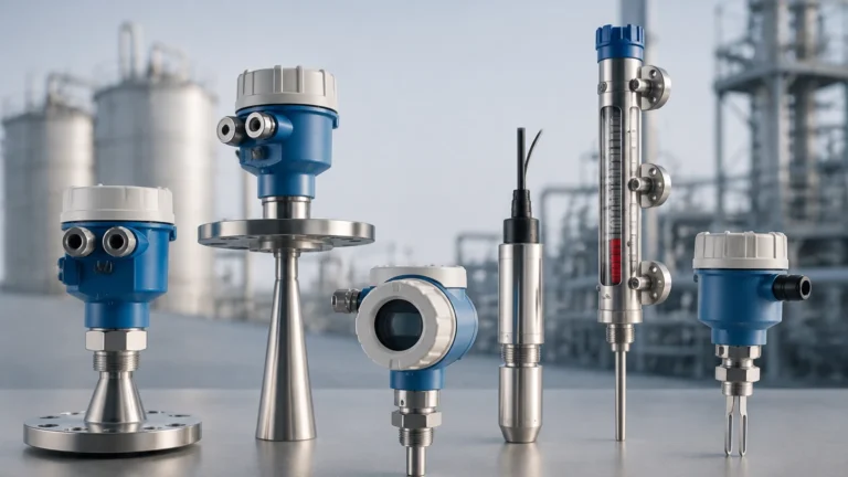
Water Flow Transmitter
Water Flow Transmitter
In industrial process control, the accurate measurement of liquid movement is as critical as monitoring the volume stored within a vessel. A water flow transmitter is a sophisticated instrument designed to measure the rate of water flow through a pipeline or open channel and convert that physical movement into a standardized electrical signal, such as 4-20mA, HART, or Modbus. This data allows for real-time monitoring, billing, and automated control in applications ranging from municipal water treatment to complex chemical processing.
While level measurement focuses on the vertical position of a liquid surface, flow measurement addresses the kinetic aspect of the fluid. Understanding the synergy between these two variables is essential for comprehensive fluid management. For instance, a facility might use a radar level meter to monitor tank inventory while simultaneously employing a water flow transmitter to track the rate of consumption or discharge. For a broader look at the instrumentation used to manage these processes, engineers often refer to the comprehensive resources available on the Main Page of industrial equipment providers.
Core Measurement Principles of Water Flow Transmitters
Before selecting a specific device, it is necessary to understand the physics governing different measurement technologies. Each principle offers distinct advantages depending on the water's purity, conductivity, and the physical constraints of the installation.
Electromagnetic Flow Measurement (Magmeters)
Electromagnetic water flow transmitters operate based on Faraday’s Law of Electromagnetic Induction. This law states that a conductor moving through a magnetic field produces an electrical voltage. In this application, the water acts as the conductor. As water flows through a pipe surrounded by magnetic coils, it generates a voltage proportional to its velocity.
Because this method requires the fluid to be electrically conductive (typically >5 μS/cm), it is ideal for raw water, wastewater, and chemical solutions. Since there are no moving parts or obstructions in the flow path, magmeters provide extremely low pressure drop and high reliability.
Ultrasonic Flow Measurement
Ultrasonic transmitters use sound waves to determine flow velocity. There are two primary types:
1. Transit-Time: These devices send ultrasonic pulses diagonally across the pipe. Pulses traveling with the flow move faster than those traveling against it. The time difference is proportional to the flow rate. This is best for clean water.
2. Doppler Effect: These sensors reflect sound waves off particles or air bubbles in the water. The frequency shift of the reflected wave indicates the velocity. This is preferred for aerated water or sludge.
Differential Pressure (DP) Flow Measurement
DP transmitters utilize Bernoulli’s principle by placing a primary element, such as an orifice plate or a Venturi tube, inside the pipe to create a localized pressure drop. The transmitter measures the pressure difference between the upstream and downstream sides of the obstruction. The square root of this pressure difference is proportional to the flow rate. While traditional, these systems are robust and well-understood in high-pressure industrial environments.
Vortex Shedding
When water flows past a non-streamlined "shredder bar" (bluff body), it creates alternating vortices (swirls) known as a Karman Vortex Street. The frequency at which these vortices are shed is directly proportional to the fluid velocity. Vortex transmitters are highly durable and perform well in high-velocity clean water applications.
Technical Selection Criteria
Choosing the right water flow transmitter requires a detailed analysis of the process conditions. Failure to match the technology to the environment can lead to measurement drift or premature sensor failure.
| Criteria | Electromagnetic | Ultrasonic (Transit-Time) | Vortex | Differential Pressure |
| :— | :— | :— | :— | :— |
| Fluid Type | Conductive liquids | Clean liquids | Clean/Low viscosity | Clean/Steam/Liquids |
| Accuracy | ±0.5% to ±0.2% | ±0.5% to ±1.0% | ±0.75% to ±1.0% | ±1.0% to ±2.0% |
| Pressure Drop | None | None | Moderate | High |
| Moving Parts | None | None | None | None (Primary element) |
| Installation | Inline | Inline or Clamp-on | Inline | Inline |
| Conductivity | Required (>5 μS/cm) | Not required | Not required | Not required |
Fluid Properties
The chemical composition of the water is the first filter for selection. For deionized (DI) water, which has very low conductivity, an electromagnetic transmitter will not function, making ultrasonic or vortex meters the better choice. Conversely, for wastewater containing solids, an electromagnetic meter is superior because it lacks internal components that could clog or erode.
Flow Profile and Reynolds Number
Most water flow transmitters assume a "fully developed" flow profile, where the velocity is highest in the center of the pipe and tapers off toward the walls. The Reynolds number (Re) helps determine if the flow is laminar or turbulent. Most industrial transmitters are calibrated for turbulent flow (Re > 4000). If the flow is too slow (laminar), accuracy may degrade significantly.
Installation Considerations and Best Practices
Even the most accurate water flow transmitter will provide erroneous data if installed incorrectly. Proper mechanical integration is the foundation of reliable data.
Straight Pipe Requirements
To ensure a stable flow profile, transmitters typically require a specific length of straight pipe both upstream and downstream of the sensor. This is usually expressed in pipe diameters (D).
* Upstream: Generally 10D to 20D (e.g., for a 100 mm pipe, 1000 mm to 2000 mm of straight pipe is needed before the meter).
* Downstream: Generally 5D.
If there are elbows, valves, or pumps near the installation point, these requirements may increase to prevent turbulence from reaching the sensor.
Pipe Orientation and Filling
For accurate measurement, the sensor must be completely submerged in the fluid.
* Vertical Upward Flow: This is the ideal orientation as it ensures the pipe remains full and air bubbles are carried away from the sensor.
* Horizontal Flow: The transmitter should be installed in a low section of the piping (a U-trap configuration) to ensure the pipe is always full. Avoid installing at the highest point of a system where air pockets can collect.
* Vertical Downward Flow: Generally avoided, as the pipe may not remain full, leading to significant measurement errors.
Grounding and Interference
Electromagnetic water flow transmitters are sensitive to electrical noise. Proper grounding of the fluid and the transmitter body to a common earth ground is essential. In plastic or lined pipes, grounding rings must be used to establish electrical contact with the water.
Limitations and Operational Challenges
While modern transmitters are highly advanced, they are not immune to environmental and physical limitations.
1. Entrained Air: Air bubbles in a water line can cause ultrasonic signals to scatter or cause electromagnetic meters to read incorrectly. Air release valves should be installed upstream if aeration is a known issue.
2. Scaling and Deposits: In hard water applications, calcium carbonate or other minerals can build up on the electrodes of a magmeter or the inner walls of a vortex meter. This changes the internal diameter of the pipe, leading to an overestimation of flow (since velocity increases for the same volume).
3. Cavitation: If the pressure in the line drops below the vapor pressure of the water, vapor bubbles form and then collapse. This can physically pit the internal surfaces of the transmitter and cause erratic readings.
4. Minimum Velocity: Most transmitters have a "low-flow cutoff." If the water is moving too slowly (typically below 0.1 m/s to 0.3 m/s), the signal-to-noise ratio becomes too low to provide a reliable measurement.
The Integration of Flow and Level Data
In many B2B industrial scenarios, a water flow transmitter is part of a larger control loop. For example, in a cooling tower application, a level switch or ultrasonic level sensor monitors the basin level. When the level drops, a valve opens to add makeup water. A flow transmitter on that makeup line verifies that water is actually moving and calculates the total volume added for chemical dosing purposes.
By combining flow data with level data, operators can perform a "mass balance" calculation. If the flow into a tank does not match the increase in level (after accounting for discharge), it indicates a potential leak or a calibration error in one of the instruments. For technical specifications on the level measurement side of this equation, visiting the Main Page provides insight into how these technologies are paired.
Frequently Asked Questions (FAQ)
Q: Can a water flow transmitter measure flow in both directions?
A: Many electromagnetic and ultrasonic transmitters are bi-directional. They can track both forward and reverse flow and provide separate totals for each. However, this must be specified during the configuration phase.
Q: How often should a water flow transmitter be calibrated?
A: For standard industrial water applications, an annual calibration check is recommended. In regulated industries like municipal drinking water or pharmaceutical processing, semi-annual calibration may be required to meet compliance standards.
Q: What is the difference between a flow meter and a flow transmitter?
A: While the terms are often used interchangeably, a flow meter usually refers to the entire assembly (sensor + display), whereas a flow transmitter specifically refers to the electronic component that converts the sensor signal into a remote output (like 4-20mA) for a PLC or DCS.
Q: Can I use a water flow transmitter for hot water or steam?
A: Standard water flow transmitters are often rated up to 80°C or 100°C. For high-temperature water or steam, specialized vortex or differential pressure transmitters with high-temperature gaskets and remote electronics are required.
Conclusion
The selection of a water flow transmitter is a balance between the physical properties of the water and the mechanical constraints of the piping system. By understanding the underlying principles—whether electromagnetic, ultrasonic, or mechanical—and adhering to strict installation guidelines regarding straight pipe runs and orientation, engineers can ensure long-term accuracy and system reliability. When integrated with high-quality level measurement instruments, these transmitters form the backbone of efficient and safe industrial fluid management.