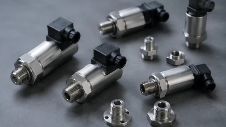
Water in Oil Detection Sensor
Water in Oil Detection Sensor
In industrial environments, the presence of water in lubricating, hydraulic, and insulating oils is a leading cause of machinery failure and process inefficiency. A water in oil detection sensor serves as a critical diagnostic tool, providing real-time data to prevent corrosion, cavitation, and the degradation of oil properties. As industries move toward predictive maintenance, understanding the technology behind these sensors is essential for selecting the right equipment for specific applications.
Water contamination typically occurs through condensation, seal leakage, or ingress during maintenance. Regardless of the source, the presence of water—even in small quantities—can significantly reduce the load-carrying capacity of oil and accelerate the oxidation of the fluid and the components it protects. This guide examines the measurement principles, selection criteria, and installation best practices for these essential industrial instruments.
Measurement Principles of Water in Oil Detection
Before selecting a sensor, it is important to understand the physical principles used to detect moisture in a hydrocarbon base. Most industrial sensors utilize one of three primary methods: capacitance, infrared spectroscopy, or conductivity.
Capacitance and Dielectric Constant
This is the most common technology for online water in oil detection sensors. It relies on the significant difference between the dielectric constant of oil (typically 2 to 5) and water (approximately 80). The sensor consists of a probe with two electrodes that form a capacitor. As the water content in the oil increases, the dielectric constant of the mixture changes, leading to a measurable change in capacitance.
Modern capacitive sensors often measure "Water Activity" ($a_w$), which represents the ratio of the actual water content to the maximum amount of water the oil can hold at a specific temperature (saturation point). This is expressed as a value between 0 (completely dry) and 1 (fully saturated).
Infrared (IR) Spectroscopy
Optical sensors use infrared light to detect water molecules. Water absorbs light at specific wavelengths in the near-infrared spectrum. By passing an IR beam through a thin film of oil and measuring the attenuation of light at these specific wavelengths, the sensor can calculate the absolute concentration of water in parts per million (ppm). This method is highly accurate and less sensitive to the chemical composition of the oil than capacitive methods, though it is often more expensive and complex to implement in-line.
Conductivity and Impedance
Conductivity sensors measure the ability of the fluid to conduct an electrical current. While pure oil is an insulator, the presence of free water significantly increases conductivity. These sensors are primarily used for detecting "free water" or large-scale ingress rather than dissolved moisture at the ppm level. They are often employed as switches to trigger alarms when a phase separation occurs.
States of Water in Oil
Selecting a water in oil detection sensor requires an understanding of how water exists within the oil. Water is found in three distinct states:
1. Dissolved Water: Molecules are dispersed individually throughout the oil, similar to humidity in the air. The oil remains clear. Most oils have a saturation point; once exceeded, the water changes state.
2. Emulsified Water: When water exceeds the saturation point and is mechanically agitated, it forms microscopic droplets suspended in the oil. This usually gives the oil a cloudy or milky appearance.
3. Free Water: This occurs when the water and oil fully separate. Because water is denser than most oils, it typically settles at the bottom of tanks or sumps.
Capacitive sensors are excellent for detecting dissolved and emulsified water, whereas conductivity-based switches are better suited for free water detection at the bottom of a reservoir.
Key Evaluation Criteria for Sensor Selection
When evaluating a water in oil detection sensor for an industrial application, several technical parameters must be confirmed to ensure reliability and accuracy.
Accuracy and Sensitivity
In critical systems like high-voltage transformers or high-speed turbines, even 50 ppm of water can be catastrophic. In these cases, high-sensitivity sensors capable of measuring low water activity are required. For general hydraulic systems, a sensor that triggers at 50% to 70% saturation may be sufficient.
Operating Temperature and Pressure
Industrial oils often operate at elevated temperatures. Sensors must be rated for the maximum process temperature, often up to 100°C (212°F) or higher. Similarly, if the sensor is installed in a pressurized lubrication line, it must withstand the system pressure, which can exceed 20 bar (290 PSI) in many hydraulic applications.
Oil Compatibility and Additives
The chemical makeup of the oil, including detergents, anti-wear additives, and rust inhibitors, can affect the dielectric constant. It is vital to ensure the sensor can be calibrated for the specific oil grade in use. Some synthetic oils have higher baseline dielectric constants than mineral oils, which must be accounted for during setup.
Output Signals and Integration
For automated monitoring, sensors should provide standard industrial outputs such as 4-20 mA analog signals, or digital protocols like Modbus RTU or IO-Link. This allows the data to be integrated into a PLC or SCADA system for trend analysis. For more information on integrating these sensors into broader industrial measurement systems, you can refer to the technical resources on the Main Page of professional instrument manufacturers like Welk.
Practical Selection Table
The following table provides a comparison of common sensor technologies based on typical industrial requirements.
| Feature | Capacitive Probe | Infrared (Optical) | Conductivity Switch |
| :— | :— | :— | :— |
| Primary Measurement | Water Activity ($a_w$) | Absolute Content (ppm) | Presence of Free Water |
| Detection Range | 0 to 100% Saturation | 10 to 5000+ ppm | Alarm (On/Off) |
| Sensitivity | High (Dissolved water) | Very High | Low (Free water only) |
| Cost | Moderate | High | Low |
| Best Application | Hydraulic & Lube Oil | Critical Process/Lab | Tank Bottom/Sump |
| Maintenance | Low | Moderate (Lens cleaning) | Low |

Installation Considerations
The performance of a water in oil detection sensor is heavily dependent on its placement within the system. Incorrect installation can lead to stagnant oil readings or false alarms.
* Representative Flow: The sensor probe should be placed in an area where there is active oil circulation. Avoid "dead legs" or the very top of a pipe where air pockets might form.
* Probe Orientation: In horizontal pipes, the sensor should ideally be installed from the side. Installing from the bottom may lead to sediment buildup on the sensor tip, while installing from the top may result in the sensor being exposed to air if the pipe is not completely full.
* Temperature Stability: Since water saturation levels are highly temperature-dependent, the sensor should ideally be installed at a point in the system where the temperature is relatively stable, or it must include an integrated temperature sensor for compensation.
* Insertion Depth: The active part of the sensor probe must be fully submerged in the oil flow. For large diameter pipes, long-reach probes may be necessary to reach the center of the flow stream.
Limitations and Potential Risks
While highly effective, water in oil detection sensors have limitations that engineers must manage:
1. Contamination of the Sensor: Over time, soot, metallic wear particles, or heavy oil additives can coat the sensor element. This may cause a "drift" in readings, requiring periodic cleaning and recalibration.
2. Temperature Shocks: Rapid changes in temperature can cause temporary inaccuracies as the sensor and the oil reach thermal equilibrium. High-quality sensors include algorithms to mitigate this, but it remains a factor in dynamic systems.
3. Salinity and Conductive Contaminants: In offshore or marine environments, the ingress of salt water significantly changes the electrical properties of the fluid compared to fresh water. Sensors must be rated for these conditions to avoid false readings.
4. Oil Aging: As oil oxidizes and ages, its base dielectric constant changes. A sensor calibrated for brand-new oil may show a slight offset after several thousand hours of oil service.
Frequently Asked Questions (FAQs)
Q: What is the difference between ppm and water activity ($a_w$)?
A: Ppm (parts per million) measures the absolute mass of water in the oil. Water activity ($a_w$) measures how close the oil is to its saturation point. $a_w$ is often more useful for maintenance because it tells you how much "room" the oil has left before free water starts to form and cause damage.
Q: How often should a water in oil detection sensor be calibrated?
A: For most industrial applications, an annual calibration check is recommended. However, if the oil type is changed or if the system experiences a major contamination event, recalibration should be performed immediately.
Q: Can these sensors detect other fluids, like coolant or fuel, in the oil?
A: Capacitive sensors are sensitive to any change in the dielectric constant. While they are optimized for water, a significant ingress of glycol (coolant) will also change the reading. However, they cannot typically distinguish between water and other polar contaminants without secondary analysis.
Q: Is it better to install the sensor in the reservoir or the return line?
A: The return line is often preferred because it provides a "real-time" look at the condition of the oil as it leaves the machinery. Reservoir installation is useful for monitoring the overall health of the stored oil but may have slower response times to sudden ingress events.
Conclusion
Implementing a water in oil detection sensor is a proactive step toward ensuring the longevity of industrial machinery. By understanding the measurement principles—primarily capacitance for dissolved moisture and conductivity for free water—engineers can select the most appropriate technology for their specific environmental conditions. Proper installation in a representative flow area and regular maintenance are key to ensuring the sensor provides the reliable data necessary for an effective predictive maintenance strategy. For those seeking specific hardware solutions and technical integration support, consulting the Main Page of an established manufacturer like Welk is the recommended next step to ensure all application-specific variables are addressed.