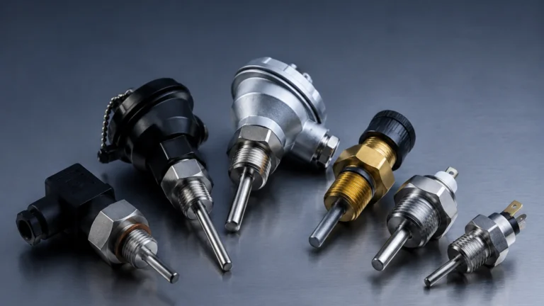
Dissolved Oxygen Analyzer
Dissolved Oxygen Analyzer
Dissolved oxygen (DO) is a critical parameter in various industrial processes, serving as a primary indicator of water quality and process efficiency. A dissolved oxygen analyzer is an instrument designed to measure the amount of gaseous oxygen (O2) dissolved in a liquid, typically water. In industrial environments such as wastewater treatment, chemical manufacturing, and power generation, maintaining precise DO levels is essential for biological activity, corrosion prevention, and regulatory compliance.
While level measurement instruments—such as those found on our Main Page—manage the volume and containment of process liquids, the dissolved oxygen analyzer ensures the chemical suitability of that liquid for its intended purpose. This guide provides a comprehensive technical overview of DO measurement principles, selection criteria, and installation best practices for engineering and maintenance professionals.
Measurement Principles of Dissolved Oxygen Analyzers
Before selecting a dissolved oxygen analyzer, it is vital to understand the underlying physics of the two primary sensing technologies: electrochemical and optical.
1. Electrochemical Sensors
Electrochemical DO sensors operate by reducing oxygen at a cathode, which creates an electrical current proportional to the partial pressure of oxygen in the liquid. These are further divided into two types:
* Polarographic Sensors: These require an external voltage (polarizing voltage) to be applied to the electrodes. They consist of a gold cathode and a silver anode immersed in a potassium chloride (KCl) electrolyte solution. A semi-permeable membrane allows oxygen to pass through while keeping the electrolyte in. These sensors typically require a "warm-up" period of 15 to 60 minutes to stabilize the polarization before accurate readings can be taken.
* Galvanic Sensors: These are self-polarizing. The electrodes are made of dissimilar metals (typically a lead anode and a silver or gold cathode). The difference in electrode potential is sufficient to reduce oxygen without an external power source. Galvanic sensors provide an immediate reading upon power-up, making them popular for portable applications and intermittent monitoring.
Both electrochemical types consume oxygen during the measurement process, meaning they require a minimum flow rate (typically 0.3 m/s or 1 ft/s) across the membrane to prevent localized oxygen depletion, which would lead to artificially low readings.
2. Optical (Fluorescence Quenching) Sensors
Optical dissolved oxygen analyzers, often referred to as Luminescent Dissolved Oxygen (LDO) sensors, utilize the principle of fluorescence quenching. The sensor cap contains a luminophore layer. When a blue light source (LED) hits this layer, it excites the luminophore, which then emits red light. If oxygen molecules are present, they collide with the excited luminophore and "quench" the fluorescence.
The analyzer measures either the intensity or the lifetime of the luminescence. Because oxygen is not consumed during this process, optical sensors do not require a minimum flow rate and are highly stable over long periods. They are increasingly becoming the industry standard for continuous process monitoring due to their lower maintenance requirements.
Key Components and System Architecture
A complete industrial dissolved oxygen analyzer system generally consists of three main components:
1. The Sensor (Probe): The primary element in contact with the process fluid. It houses the electrodes/electrolyte or the optical sensing cap.
2. The Transmitter (Controller): The electronic unit that processes the raw signal from the sensor. It provides a digital display and outputs the data via 4-20mA, RS485 (Modbus), or HART protocols for integration into a PLC or SCADA system.
3. The Mounting Assembly: Hardware used to secure the sensor in the tank or pipe, such as immersion rods, flow-through cells, or retractable housings.
Selection Criteria for Industrial Applications
Choosing the right dissolved oxygen analyzer requires an evaluation of the process environment and the required accuracy. The following table compares the two primary technologies based on common industrial needs.
Selection Table: Electrochemical vs. Optical DO Analyzers
| Feature | Electrochemical (Polarographic/Galvanic) | Optical (Luminescence) |
| :— | :— | :— |
| Flow Requirement | Minimum flow required (0.3 m/s) | No flow required |
| Maintenance | High (Membrane/Electrolyte replacement) | Low (Annual cap replacement) |
| Calibration Frequency | Frequent (Weekly/Monthly) | Infrequent (Quarterly/Bi-annually) |
| Response Time | Fast (30–60 seconds) | Moderate (45–90 seconds) |
| Sensitivity to H2S | High (Can poison the sensor) | None |
| Initial Cost | Lower | Higher |
| Operating Life | 1–3 years for sensor body | 5–10 years for sensor body |
Application-Specific Considerations
* Wastewater Treatment (Aeration Tanks): Optical sensors are preferred here because they are less susceptible to fouling and do not require constant flow, which can be inconsistent in large basins.
* Boiler Feedwater: In high-pressure steam systems, DO must be kept in the parts-per-billion (ppb) range to prevent corrosion. Specialized "trace-level" polarographic sensors are often used for their extreme sensitivity at near-zero levels.
* Aquaculture: Galvanic sensors are often chosen for their portability and lack of warm-up time, though optical sensors are gaining ground for permanent installations.
Installation Guidelines and Best Practices
Proper installation is critical for the longevity and accuracy of a dissolved oxygen analyzer. Incorrect placement can lead to air bubble interference or sensor damage.
1. Avoid Air Pockets: In pipe installations, the sensor should be installed on the side or bottom of the pipe, never at the top where air can trap. In tanks, avoid areas directly above aeration diffusers, as the sensor will measure the air bubbles rather than the dissolved oxygen.
2. Submergence Depth: For immersion installations, ensure the sensor is submerged at least 300 mm (12 inches) below the surface to avoid atmospheric oxygen interference caused by surface turbulence.
3. Flow Orientation: For electrochemical sensors, the membrane should face into the flow to ensure a constant supply of fresh sample. For optical sensors, orientation is less critical, but the sensing face should be positioned to minimize debris buildup.
4. Cable Management: Use shielded cables for signal transmission to prevent electromagnetic interference (EMI) from large motors or pumps. Ensure the cable length does not exceed the manufacturer’s specifications to avoid signal degradation.
5. Temperature Compensation: DO solubility is highly dependent on temperature. Ensure the analyzer has an integrated Temperature Compensator (NTC or Pt100/Pt1000) and that the sensor has reached thermal equilibrium with the process liquid before calibration.
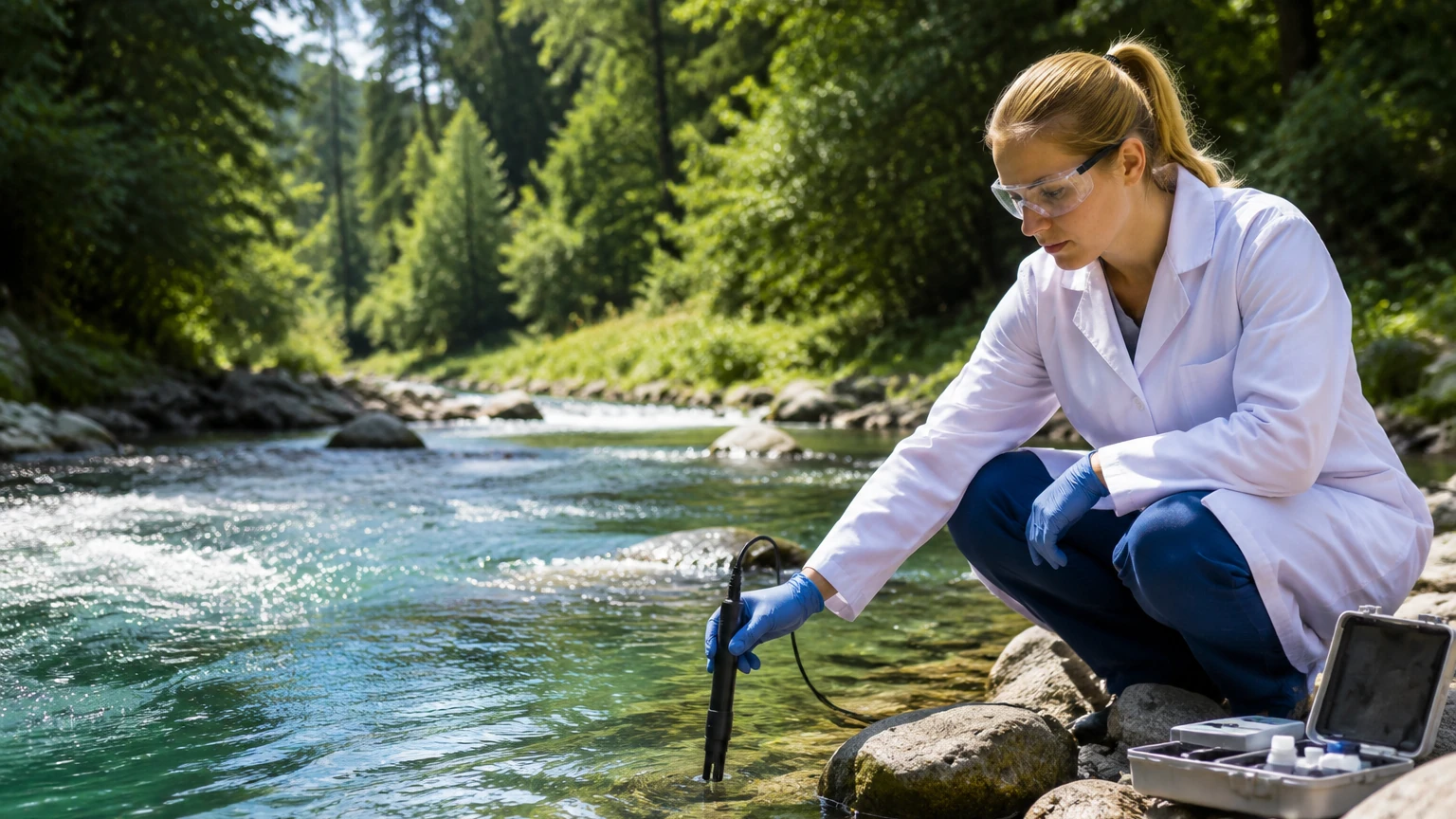
Maintenance and Calibration Procedures
Maintenance schedules vary significantly by technology.
For Electrochemical Sensors:
* Membrane Inspection: Check for tears, fouling, or air bubbles behind the membrane. Membranes should typically be replaced every 3 to 6 months depending on the harshness of the process.
* Electrolyte Replenishment: Refill the electrolyte solution whenever the membrane is changed or if the signal becomes unstable.
* Anode Cleaning: If the silver anode becomes tarnished (blackened), it may require gentle cleaning with an abrasive cloth as per the manufacturer's instructions.
For Optical Sensors:
* Sensing Cap Replacement: The luminophore layer degrades over time. Most caps last 12 to 24 months. The transmitter will usually provide a diagnostic alert when the cap's light intensity reaches a critical threshold.
* Cleaning: Use a soft cloth or a gentle water spray to remove biofilm or scaling from the cap. Avoid harsh chemicals that could damage the optical coating.
Calibration Methods:
1. Air Calibration (Most Common): The sensor is held in water-saturated air (e.g., just above the water surface in a tank). This is a reliable method because the partial pressure of oxygen in air is constant and well-defined.
2. Winkler Titration: A laboratory chemical analysis of a grab sample. This is used to verify the analyzer's accuracy in-situ, though it is subject to sampling errors.
3. Zero-Point Calibration: Immersing the sensor in an oxygen-free solution (typically sodium sulfite dissolved in water). This is essential for trace-level measurements in power plants.
Limitations and Common Challenges
While highly effective, dissolved oxygen analyzers have limitations that engineers must account for:
* Pressure Sensitivity: DO measurement is a measurement of partial pressure. If the process pressure changes significantly (e.g., in a pressurized pipeline), the analyzer must be pressure-compensated, or the reading will be inaccurate.
* Salinity Interference: Salt reduces the solubility of oxygen. In seawater or brackish water applications, the salinity value must be entered into the transmitter to correct the mg/L (concentration) reading.
* Chemical Interference: For electrochemical sensors, gases like Hydrogen Sulfide (H2S), Chlorine (Cl2), and Carbon Dioxide (CO2) can permeate the membrane and react with the electrolyte or electrodes, causing drift or sensor failure.
* Biofouling: In wastewater and environmental monitoring, the growth of algae or bacteria on the sensor face is the most common cause of measurement drift. Automatic cleaning systems (air blast or water spray) are highly recommended for these applications.
Frequently Asked Questions (FAQs)
Q: How often should I calibrate my dissolved oxygen analyzer?
A: For optical sensors in clean water, every 3-6 months is often sufficient. For electrochemical sensors in wastewater, weekly or bi-weekly calibration may be necessary due to membrane fouling and electrolyte depletion.
Q: Can I use a DO analyzer in high-temperature liquids?
A: Most standard DO sensors are rated up to 50°C (122°F). Specialized high-temperature versions are available for processes up to 100°C (212°F), but extreme temperatures will significantly shorten the lifespan of membranes and optical caps.
Q: What is the difference between % Saturation and mg/L?
A: % Saturation measures the partial pressure of oxygen relative to the maximum amount of oxygen that can be dissolved in water at that specific temperature and pressure. mg/L (or ppm) measures the actual mass concentration of oxygen. Most industrial transmitters can display both.
Q: Why is my DO reading higher than the actual oxygen level?
A: This is often caused by air bubbles trapped against the sensor membrane or cap. It can also occur if the sensor was calibrated in dry air rather than water-saturated air, or if the temperature compensation element is failing.
Conclusion
A dissolved oxygen analyzer is a vital tool for process control, ensuring that aeration systems are optimized and that water quality meets stringent industrial standards. By understanding the differences between electrochemical and optical technologies, and by adhering to rigorous installation and maintenance protocols, facilities can achieve reliable, long-term monitoring results.
For industrial operators, integrating DO analysis with other process variables—such as liquid level, flow, and pressure—provides a holistic view of the system. For more information on primary process instrumentation and measurement solutions, please visit our Main Page to review product options and application support.