Water Level Control System
Water Level Control System
In industrial environments, a water level control system is a fundamental component of process automation. These systems are designed to monitor and manage the volume of water within tanks, reservoirs, or open channels, ensuring that levels remain within specific operational parameters. Effective control prevents catastrophic events such as tank overflows, which can lead to environmental hazards and equipment damage, as well as dry-run conditions that can destroy expensive pumping systems.
For engineers and facility managers, selecting the right water level control system requires a deep understanding of the underlying measurement technologies and the specific requirements of the application, whether it be in water treatment, chemical processing, or oil and gas production. This guide examines the principles of level measurement, system architecture, and practical selection criteria for industrial implementation.
Measurement Principles in Water Level Control
Before designing a control system, one must understand how the level is actually measured. Industrial level measurement typically falls into two categories: contact and non-contact. Each principle has distinct advantages depending on the physical properties of the water (temperature, pressure, conductivity) and the environment of the vessel.
Ultrasonic Level Measurement
Ultrasonic sensors operate on the "Time of Flight" (ToF) principle. The sensor emits high-frequency sound pulses that travel through the air toward the water surface. When the pulse hits the surface, it reflects back to the sensor. By measuring the time it takes for the echo to return, the system calculates the distance to the water surface. Since the height of the tank is known, the water level is easily derived.
* Pros: Non-contact, no moving parts, relatively low cost.
* Cons: Affected by foam, heavy vapor, and extreme temperature fluctuations which change the speed of sound.
Radar Level Measurement
Similar to ultrasonic, radar sensors use the ToF principle but utilize electromagnetic waves (microwaves) instead of sound. Radar waves travel at the speed of light and are largely unaffected by air temperature, pressure, or the presence of dust and vapor. Radar is often preferred for high-precision applications or where the atmosphere above the water is volatile.
* Pros: Highly accurate, works in vacuum or high pressure, unaffected by atmospheric conditions.
* Cons: Higher initial capital expenditure compared to ultrasonic.
Hydrostatic Level Measurement
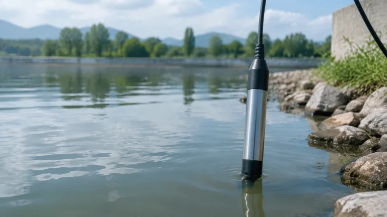
Hydrostatic transmitters measure the pressure exerted by the liquid column above the sensor. The principle is based on the formula $P = \rho gh$ (Pressure = Density × Gravity × Height). In most water applications, density is constant, meaning the pressure is directly proportional to the level. These sensors are typically submerged at the bottom of the tank or mounted to a side flange.
* Pros: Reliable for deep wells and vented tanks, easy to install.
* Cons: Can be affected by changes in liquid density or pressurized tank headspaces (unless differential pressure is used).
Magnetic Level Gauges and Switches
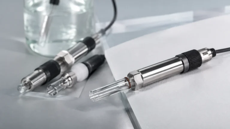
Magnetic level gauges utilize a float containing a magnet that moves with the water level inside a bypass chamber. This magnet flips external flags for visual indication and can trigger magnetic switches or continuous transmitters. This is a robust mechanical solution that provides both local visualization and remote signaling.
Components of a Water Level Control System
A complete water level control system is more than just a sensor; it is an integrated loop consisting of three primary stages: sensing, controlling, and acting.
1. The Sensor (Input): This is the primary element (e.g., a radar level meter or hydrostatic transmitter) that provides a continuous signal (typically 4-20mA or digital RS485/HART) or a point-level signal (switch) to the controller.
2. The Controller (Logic): This is the "brain" of the system, often a Programmable Logic Controller (PLC) or a dedicated digital level controller. It receives the signal from the sensor, compares it against user-defined setpoints (High-High, High, Low, Low-Low), and determines the necessary action.
3. The Actuator (Output): Based on the controller’s command, an actuator performs a physical action. This usually involves starting or stopping a pump, or opening and closing a motorized or pneumatic valve to regulate the inflow or outflow of water.
Practical Selection Table
Choosing the right technology depends on the specific constraints of the project. The following table provides a comparison of common industrial level measurement technologies used in water control systems.
| Technology | Measurement Range | Accuracy | Typical Application | Environmental Limitations |
| :— | :— | :— | :— | :— |
| Ultrasonic | 0.3m – 15m (1ft – 49ft) | ±0.25% | Water tanks, open channels | Foam, heavy steam, vacuum |
| Radar (80GHz) | 0.1m – 30m+ (0.3ft – 98ft+) | ±2mm | Chemical storage, high-precision tanks | Extremely high cost for basic use |
| Hydrostatic | 1m – 200m (3ft – 656ft) | ±0.5% | Deep wells, reservoirs, lift stations | Sludge buildup, pressurized tanks |
| Magnetic Gauge | 0.3m – 6m (1ft – 20ft) | ±5mm | Boiler drums, industrial process tanks | High-viscosity liquids, magnetic debris |
| Level Switch | Point Level Only | N/A | Pump dry-run protection, overflow alarm | Moving parts can foul in dirty water |
Installation Considerations
The reliability of a water level control system is heavily dependent on proper installation. Even the most advanced radar meter will fail if mounted incorrectly.
Mounting Location
Sensors should be mounted away from the tank's inlet to avoid turbulence and the "noise" created by incoming water. For non-contact sensors like ultrasonic or radar, the beam must have a clear path to the water surface, free from internal obstructions like ladders, agitators, or heating coils.
Dead Zones (Blocking Distance)
Every ultrasonic and radar sensor has a "dead zone" or "blocking distance" directly beneath the sensor face (typically 0.1m to 0.5m). If the water level rises into this zone, the sensor will provide an erroneous reading. It is critical to mount the sensor high enough so that the maximum possible water level never enters the dead zone.
Stilling Wells and Bypass Chambers
In applications with significant surface turbulence or foam, a stilling well (a vertical pipe submerged in the water) can be used to provide a calm surface for the sensor to measure. Similarly, magnetic level gauges use a bypass chamber to isolate the float from the main tank's turbulence.
Cable Protection and Grounding
For hydrostatic transmitters, the vented cable is a critical component that allows the sensor to compensate for atmospheric pressure. This cable must be protected from kinks and moisture ingress. Furthermore, all electronic level instruments must be properly grounded to prevent signal interference and protect against lightning strikes in outdoor installations.
System Limitations and Common Risks
While modern water level control systems are highly advanced, they are not without limitations. Engineers must account for the following risks during the design phase:
* Foam and Vapor: Heavy foam on the water surface can absorb ultrasonic signals, leading to a "loss of echo." In such cases, radar or hydrostatic sensors are more reliable.
* Sediment and Scaling: In wastewater applications, sediment can accumulate on hydrostatic sensor diaphragms, leading to drift in accuracy. Regular cleaning or the use of flush-diaphragm sensors is necessary.
* Power Supply Fluctuations: Industrial environments often have unstable power grids. Using a regulated 24V DC power supply and surge protection is vital for the longevity of the control electronics.
* Signal Interference: Long cable runs between the sensor and the PLC can pick up electromagnetic interference (EMI). Using shielded twisted-pair cables and maintaining separation from high-voltage power lines is a standard requirement.
To ensure you are selecting the most appropriate hardware for your specific infrastructure, you can Review product options and application support at the Welk Main Page.
Frequently Asked Questions (FAQ)
Q: Can I use one sensor for both continuous monitoring and high-level alarms?
A: While a continuous sensor (like radar) can trigger an alarm via the PLC, safety standards often require a redundant, independent level switch (like a float switch or tuning fork) for high-level alarms to ensure protection even if the primary sensor or PLC fails.
Q: How often should a water level control system be calibrated?
A: For most industrial water applications, an annual calibration check is sufficient. However, in critical chemical processes or billing applications (custody transfer), semi-annual calibration may be required.
Q: What is the difference between 2-wire and 4-wire transmitters?
A: A 2-wire transmitter uses the same two wires for both power and the 4-20mA signal, making it easier to install. A 4-wire transmitter has separate pairs for power and signal, which is often required for high-power devices like certain types of radar or when using AC power.
Q: How does temperature affect hydrostatic level sensors?
A: Temperature changes can affect the density of the water and the expansion of the sensor components. High-quality hydrostatic sensors include internal temperature compensation to mitigate these effects.
Conclusion
Implementing a robust water level control system is an essential investment for any industrial facility dealing with water management. By understanding the measurement principles—from the simplicity of hydrostatic pressure to the precision of 80GHz radar—and adhering to strict installation guidelines, organizations can achieve high levels of operational efficiency and safety. When designing your system, always consider the specific environmental challenges of your site and prioritize technologies that offer the best balance of accuracy, reliability, and ease of maintenance.