Water Level Measuring Devices
Water Level Measuring Devices
In industrial process automation, the accurate monitoring of liquid levels is a fundamental requirement for operational safety, inventory management, and process efficiency. Water level measuring devices encompass a broad range of technologies, each engineered to address specific environmental conditions, tank geometries, and fluid characteristics. Whether managing municipal water treatment, chemical processing tanks, or cooling towers in power plants, selecting the appropriate instrumentation requires a deep understanding of the underlying physics and the operational constraints of the site.
This guide provides a technical overview of the primary technologies used in modern industrial water level measurement, offering a framework for selection based on performance, reliability, and cost-effectiveness.
Understanding Measurement Principles
Before selecting a device, engineers must distinguish between the two primary categories of level measurement: continuous measurement and point level detection. Continuous measurement provides real-time data across the entire range of a vessel, while point level detection (switches) indicates when water reaches a specific high or low threshold.
The physical principles used to derive level data generally fall into three categories:
1. Time-of-Flight (ToF): These devices emit a signal (sound or electromagnetic) and measure the time it takes for the signal to reflect off the water surface and return to the sensor. This includes ultrasonic and radar technologies.
2. Hydrostatic Pressure: This method measures the force exerted by the liquid column above a sensor. Since pressure is proportional to the height of the liquid (based on its density), the level can be calculated precisely.
3. Mechanical/Physical Interaction: These devices use buoyancy (floats) or electrical properties (capacitance/conductivity) to determine the level. Magnetic level gauges and float switches fall into this category.
Non-Contact Measurement Technologies
Non-contact sensors are often preferred in applications where the water may be corrosive, contain debris, or where maintenance access is limited. Because the sensor does not touch the liquid, it is less prone to fouling and chemical wear.
Ultrasonic Level Sensors
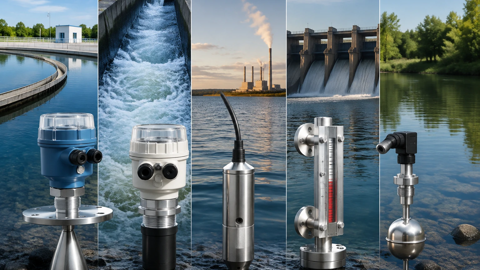
Ultrasonic sensors emit high-frequency sound waves (typically 20 kHz to 200 kHz). The sensor measures the time interval between the emission of the pulse and the reception of the echo.
* Best For: Open channels, sumps, and atmospheric tanks containing clean or slightly dirty water.
* Advantages: Cost-effective, easy to install, and no moving parts.
* Limitations: Sound waves are affected by air temperature, heavy foam, and steam. In high-pressure or vacuum environments, ultrasonic waves cannot propagate effectively.
Radar Level Meters
Radar technology uses high-frequency electromagnetic waves (microwave pulses). Unlike sound waves, microwaves are not affected by air temperature, pressure, or vacuum conditions. Radar units can be divided into non-contact (pulsed or FMCW) and guided wave radar (GWR).
* Best For: Process tanks with steam, dust, or turbulence, and applications requiring high precision over long distances (up to 70 meters or more).
* Advantages: Extremely accurate (up to ±1 mm), immune to vapor and temperature fluctuations, and capable of penetrating non-metallic tank roofs.
* Limitations: Higher initial capital expenditure compared to ultrasonic or hydrostatic options.
Contact and Pressure-Based Measurement
Contact-based devices are often more robust in turbulent environments or where surface foam would interfere with a signal reflection.
Hydrostatic Level Transmitters
These devices operate on the principle that the pressure at the bottom of a liquid column is equal to the height of the column multiplied by the specific gravity of the liquid and the constant of gravity ($P =
ho gh$). For water, a 10.2-meter column exerts approximately 1 bar (14.5 psi) of pressure.
* Submersible Transmitters: These are lowered into the water (e.g., in deep wells or reservoirs) and use a vented cable to compensate for atmospheric pressure changes.
* External Transmitters: Mounted to the side or bottom of a tank via a flange or threaded connection.
* Best For: Deep wells, boreholes, and sealed tanks where non-contact sensors cannot be mounted at the top.
Guided Wave Radar (GWR)
GWR uses a probe (rod or cable) that extends into the liquid. The radar pulse travels along the probe, reflects off the water surface, and returns. This is a contact-based version of radar that is highly effective in narrow tanks or where internal obstructions might cause false echoes for non-contact radar.
Mechanical and Visual Level Indicators
For many industrial applications, a local visual indication is required for safety backups or manual monitoring.
Magnetic Level Gauges
A magnetic level gauge consists of a bypass chamber attached to the side of a tank. A float containing a permanent magnet moves up and down with the water level. Outside the chamber, a series of bi-color magnetic flaps flip as the float passes, providing a clear visual representation of the level. These can be equipped with reed switches or transmitters for remote signal output.
* Best For: High-pressure boilers, chemical storage, and applications where power failure must not result in a loss of level visibility.
* Advantages: Highly durable, requires no power for visual indication, and handles high temperatures and pressures well.
Selection Guide for Industrial Water Level Applications
Choosing between various water level measuring devices requires a comparison of technical specifications against application needs. The following table summarizes the key selection criteria.
| Technology | Accuracy | Range (m) | Max Temp (°C) | Max Pressure (Bar) | Typical Application |
| :— | :— | :— | :— | :— | :— |
| Ultrasonic | ±0.25% | 0.3 – 15 | 80 | 3 | Open sumps, water tanks |
| Radar (80GHz) | ±1 mm | 0.1 – 120 | 250+ | 100+ | Process vessels, silos |
| Hydrostatic | ±0.1% | 1 – 500 | 100 | N/A (Depth) | Deep wells, reservoirs |
| Magnetic Gauge | ±5 mm | 0.3 – 6 | 400 | 200 | Boilers, chemical tanks |
| Guided Wave Radar| ±2 mm | 0.3 – 30 | 400 | 400 | Narrow tanks, bypass pipes |
For more detailed technical specifications and to explore specific models, engineers can Review product options and application support to match hardware with their specific process requirements.
Installation Guidelines and Best Practices
Proper installation is as critical as device selection. Even the most advanced sensor will fail if positioned incorrectly.
1. Avoid the "Dead Zone": All top-mounted sensors (ultrasonic and radar) have a blocking distance or dead zone directly beneath the sensor where measurements are not possible. Ensure the sensor is mounted high enough so the maximum water level never enters this zone.
2. Positioning Relative to Inlets: Never install a level sensor directly above a fill pipe. The turbulence and falling liquid will cause erratic readings or signal loss.
3. Stilling Wells: In tanks with heavy agitation or surface foam, a stilling well (a vertical pipe that stabilizes the water surface) can be used to provide a clean measurement area for radar or ultrasonic sensors.
4. Submersible Cable Protection: For hydrostatic sensors in deep wells, ensure the vented cable is not kinked. Use a conduit if the water contains high levels of debris that could damage the cable jacket.
5. Orientation: Ensure ultrasonic and radar sensors are mounted perfectly perpendicular to the water surface to maximize the strength of the return echo.
Limitations and Operational Risks
While modern instrumentation is highly reliable, certain environmental factors can introduce risks:
* Foam: Heavy, thick foam can absorb ultrasonic and radar signals, leading to a "loss of echo" error. In these cases, hydrostatic or guided wave radar is preferred.
* Build-up: In wastewater applications, grease or mineral build-up on the sensor face can attenuate signals. Regular maintenance or the use of self-cleaning (teflon-coated) sensors may be necessary.
* Vapor and Condensation: While radar is mostly immune, heavy condensation on an ultrasonic transducer face can block the sound pulse. Some sensors feature a heated face or a "drip-off" design to mitigate this.
* Tank Geometry: Internal structures like agitators, ladders, or heating coils can create false echoes. Modern radar software allows for "False Echo Suppression," where the device learns the tank's internal profile and ignores static reflections.
Frequently Asked Questions
Q: Can I use an ultrasonic sensor for boiling water?
A: Generally, no. Boiling water creates heavy steam and temperature gradients that significantly alter the speed of sound, leading to large measurement errors. Radar or hydrostatic sensors are better suited for these conditions.
Q: What is the difference between 26GHz and 80GHz radar?
A: 80GHz radar has a much narrower beam angle, which allows it to avoid internal obstructions and provides better performance in small tanks or narrow nozzles. 26GHz is often used for larger, less complex applications.
Q: How often do hydrostatic sensors need calibration?
A: In clean water, hydrostatic sensors are very stable and may only need calibration every 12 to 24 months. However, in applications with high sediment, the sensor diaphragm should be inspected regularly for damage or clogging.
Q: Is guided wave radar better than non-contact radar?
A: Not necessarily "better," but different. GWR is superior in low-dielectric liquids (like oils) or in narrow bypass chambers. Non-contact radar is superior for corrosive liquids where you want to avoid any contact with the probe.
Conclusion
Selecting the right water level measuring devices requires balancing the physical properties of the installation site with the required precision and budget. For simple atmospheric water storage, ultrasonic or hydrostatic sensors offer excellent value. For complex industrial processes involving high pressure, steam, or narrow vessels, radar and magnetic level gauges provide the necessary reliability and safety margins.
For a comprehensive range of industrial instrumentation and expert guidance on system integration, visit the Main Page of Welk's industrial catalog to find the optimal solution for your facility’s needs.