Waterline Controls
Waterline Controls
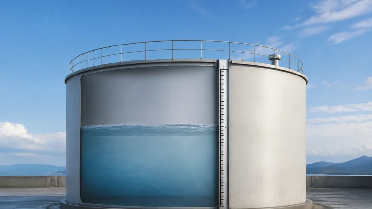
In industrial process management, the term "waterline controls" refers to the integrated systems and instrumentation used to maintain a specific liquid level within a vessel, tank, or reservoir. Whether managing the cooling water for a power plant, the boiler feed for a manufacturing facility, or the storage levels in a municipal water treatment plant, precise control of the waterline is essential for operational safety, efficiency, and equipment longevity.
Modern waterline controls have evolved from simple mechanical floats to sophisticated electronic systems utilizing radar, ultrasonic, and hydrostatic technologies. Selecting the correct technology requires a deep understanding of the underlying physics of measurement and the specific environmental constraints of the application. This guide provides a technical overview of level measurement principles, selection criteria, and installation best practices for industrial waterline management.
Core Measurement Principles for Level Control
Before selecting a control system, it is necessary to understand how different sensors detect the waterline. Each principle offers distinct advantages depending on the physical properties of the medium and the vessel environment.
Hydrostatic Pressure Measurement
Hydrostatic level transmitters operate on the principle that the pressure at a specific point in a static liquid is proportional to the height of the liquid column above it. The relationship is defined by the formula:
P = ρ × g × h
Where *P* is pressure, *ρ* (rho) is the density of the liquid, *g* is the gravitational constant, and *h* is the height of the liquid.
In waterline controls, a submersible pressure transducer or a flange-mounted transmitter measures this pressure. Since the density of water is relatively constant (approximately 1,000 kg/m³ at standard temperatures), the pressure reading provides a highly reliable linear output of the water level. This method is particularly effective in deep wells, vented tanks, and open reservoirs.
Ultrasonic (Time-of-Flight)
Ultrasonic sensors are non-contact devices that emit high-frequency sound pulses toward the water surface. The sensor measures the time it takes for the pulse to travel to the surface and reflect back to the transducer. Because the speed of sound in air is known (approximately 343 m/s at 20°C), the distance can be calculated.
Ultrasonic waterline controls are favored for their low maintenance requirements, as no parts come into contact with the water. However, they are sensitive to air temperature fluctuations, heavy foam, and steam, which can attenuate or deflect the sound waves.
Radar (Microwave) Technology
Similar to ultrasonic sensors, radar level meters use the time-of-flight principle but employ electromagnetic microwave pulses instead of sound waves. These pulses travel at the speed of light and are virtually unaffected by temperature, pressure, or the presence of vapors.
High-frequency radar (such as 80 GHz) provides a narrow beam angle, allowing for precise measurement even in narrow tanks with internal obstructions. Radar is often considered the "gold standard" for critical waterline controls where high accuracy (within ±1 mm) is required.
Magnetic Level Gauges
Magnetic level indicators use a float containing an internal magnet that moves with the waterline inside a bypass chamber. As the float rises or falls, it flips magnetic flaps or actuates a reed switch/transmitter mounted outside the chamber. This provides both a local visual indication and an electronic signal for remote control. This technology is robust and ideal for high-pressure or high-temperature water applications, such as boiler drum level control.
Key Evaluation Criteria for Sensor Selection
Choosing the right waterline controls involves more than just selecting a measurement principle. Engineers must evaluate several operational factors to ensure long-term reliability.
1. Accuracy and Repeatability: For simple overflow prevention, a repeatability of ±10 mm may suffice. However, for process dosing or custody transfer, high-precision radar with ±2 mm accuracy may be necessary.
2. Fluid Characteristics: Is the water deionized, brackish, or laden with chemicals? High salinity can increase the conductivity of the water, affecting certain probe-based sensors, while corrosive additives may require PVDF or PTFE-coated sensors.
3. Environmental Conditions: In outdoor reservoirs, sensors must account for ambient temperature swings and potential ice formation. In indoor industrial settings, electromagnetic interference (EMI) from large motors can disrupt signal integrity if not properly shielded.
4. Tank Geometry: The presence of agitators, ladders, or inlet pipes can create false echoes for non-contact sensors. In these cases, guided wave radar or stilling wells may be required to shield the measurement area.
Comparison of Waterline Control Technologies
The following table summarizes the performance characteristics of common technologies used in waterline controls.
| Technology | Contact Type | Accuracy | Best For | Limitations |
| :— | :— | :— | :— | :— |
| Hydrostatic | Contact | High (±0.1% – 0.5%) | Vented tanks, deep wells | Density changes affect accuracy |
| Ultrasonic | Non-contact | Moderate (±0.25%) | Wastewater, open channels | Sensitive to foam and steam |
| Radar | Non-contact | Very High (±1mm – 2mm) | Process tanks, high temp | Higher initial cost |
| Magnetic | Contact | Moderate | Boilers, high pressure | Moving parts can wear over time |
| Capacitance | Contact | Moderate | Small tanks, clean water | Requires constant dielectric |
Installation Best Practices and Considerations
Proper installation is as critical as the choice of instrument. Even the most advanced waterline controls will fail if the sensor is positioned incorrectly.
Avoiding the "Dead Zone"
All non-contact sensors (ultrasonic and radar) have a "dead zone" or "blocking distance" directly beneath the transducer where measurements cannot be taken. For example, if an ultrasonic sensor has a 0.3-meter dead zone, the tank can never be filled to within 0.3 meters of the sensor face without losing the signal. Installers must ensure the sensor is mounted high enough to accommodate the maximum expected waterline.
Stilling Wells and Bypass Chambers
In applications with significant turbulence or surface foam, a stilling well (a vertical pipe submerged in the liquid) can be used to provide a calm surface for measurement. For magnetic gauges, the bypass chamber serves a similar purpose, isolating the float from the main flow of the tank.
Mounting Angles and Obstructions
Non-contact sensors should be mounted perpendicular to the water surface. Even a small tilt can cause the reflected signal to miss the receiver. Furthermore, sensors should be placed away from the tank wall (typically at least 200 mm to 500 mm depending on the beam angle) to avoid "ringing" or parasitic reflections from the tank seams.
Common Risks and Operational Limitations
When implementing waterline controls, engineers must account for potential failure points that can lead to dry-running pumps or tank overflows.
* Scaling and Fouling: In hard water applications, calcium carbonate deposits can build up on hydrostatic diaphragms or ultrasonic transducers. Regular inspection and the use of flush-diaphragm sensors can mitigate this risk.
* Turbulence and Waves: Rapid filling or the use of mixers creates surface waves that can cause "chatter" in level switches. Implementing a time-delay relay or using software damping in the transmitter can stabilize the output signal.
* Vapor and Condensation: In hot water tanks, condensation can form on the face of an ultrasonic sensor, blocking the signal. Radar is generally immune to this, but for ultrasonic systems, a heater or a specialized "drip-off" transducer face may be necessary.
Frequently Asked Questions (FAQ)
Q: Can I use a hydrostatic transmitter in a pressurized tank?
A: Only if you use a differential pressure (DP) transmitter. A standard hydrostatic sensor measures the weight of the water plus the air pressure above it. In a pressurized tank, you must subtract the top pressure to accurately determine the waterline.
Q: How often do waterline controls need calibration?
A: This depends on the technology. Radar and ultrasonic sensors are generally stable for several years. Hydrostatic sensors may require annual calibration due to potential sensor drift or changes in water density.
Q: What is the benefit of a 4-20mA signal over a simple switch?
A: A 4-20mA signal provides continuous level data, allowing for sophisticated PID control and trend analysis. A switch only provides "high" or "low" alerts. Continuous monitoring allows you to predict when a tank will be empty and adjust flow rates accordingly.
Conclusion
Effective waterline controls are the backbone of industrial fluid management. By understanding the physics of hydrostatic pressure, sound reflection, and microwave propagation, engineers can select the most resilient and accurate system for their specific needs. Whether the priority is the non-contact reliability of radar or the simple, robust nature of a magnetic gauge, matching the instrument to the environment is the key to operational success.
For those seeking to integrate these technologies into their existing infrastructure, it is advisable to consult with specialists who can provide customized solutions tailored to specific industrial requirements. To explore a comprehensive range of level measurement instruments and technical specifications, Main Page for more information. To further refine your system, you may Review product options and application support to ensure your waterline controls meet the highest standards of accuracy and safety.