Flow Rate Meters
Flow Rate Meters
In the landscape of industrial process control, the ability to quantify the movement of fluids through a system is as critical as monitoring the volume stored within a vessel. Flow rate meters are precision instruments designed to measure the volume or mass of a fluid—whether liquid, gas, or steam—passing through a specific point per unit of time. For engineers and facility managers, selecting the appropriate flow measurement technology is essential for optimizing production efficiency, ensuring safety, and maintaining regulatory compliance.
While level measurement focuses on the vertical position of a substance within a tank, flow measurement tracks its kinetic progress through a process. In many applications, such as water treatment or chemical processing, these two measurements are interdependent. This guide provides a comprehensive technical overview of flow rate meters, their operating principles, and the criteria for selecting the right instrument for industrial environments.
Fundamental Principles of Flow Measurement
Before selecting a meter, it is necessary to understand the physical principles that govern how these devices interact with the fluid. Flow measurement is generally categorized into volumetric flow (measuring the space the fluid occupies) and mass flow (measuring the actual weight of the fluid). Most industrial applications rely on volumetric measurement, which can be converted to mass flow if the fluid density is constant.
Differential Pressure (DP)
Differential pressure meters operate on Bernoulli’s principle. By introducing a restriction in the pipe—such as an orifice plate, Venturi tube, or flow nozzle—the meter creates a pressure drop. The square root of the pressure difference between the upstream and downstream sides is proportional to the flow rate. These are among the most common flow rate meters due to their simplicity and lack of moving parts.
Velocity-Based Measurement
Velocity meters measure the speed of the fluid at one or more points to calculate the total volume. Common examples include:
- Electromagnetic: Based on Faraday’s Law of Induction, these meters use magnetic fields to measure the velocity of conductive liquids. As the liquid moves through the field, it generates a voltage proportional to its speed.
- Ultrasonic: These utilize sound waves. Transit-time ultrasonic meters measure the time difference between pulses sent upstream and downstream. Doppler ultrasonic meters measure the frequency shift reflected off particles or bubbles in the fluid.
- Turbine: A rotor is placed in the flow stream. The fluid's kinetic energy spins the rotor at a speed proportional to the velocity.
Oscillatory and Vortex Shedding
Vortex meters utilize the Von Kármán effect. When a fluid meets a "bluff body" (a non-streamlined object), it creates alternating vortices. The frequency at which these vortices are shed is directly proportional to the fluid velocity. These are highly valued for their durability in steam and high-temperature gas applications.
Integrating Level Measurement for Open Channel Flow
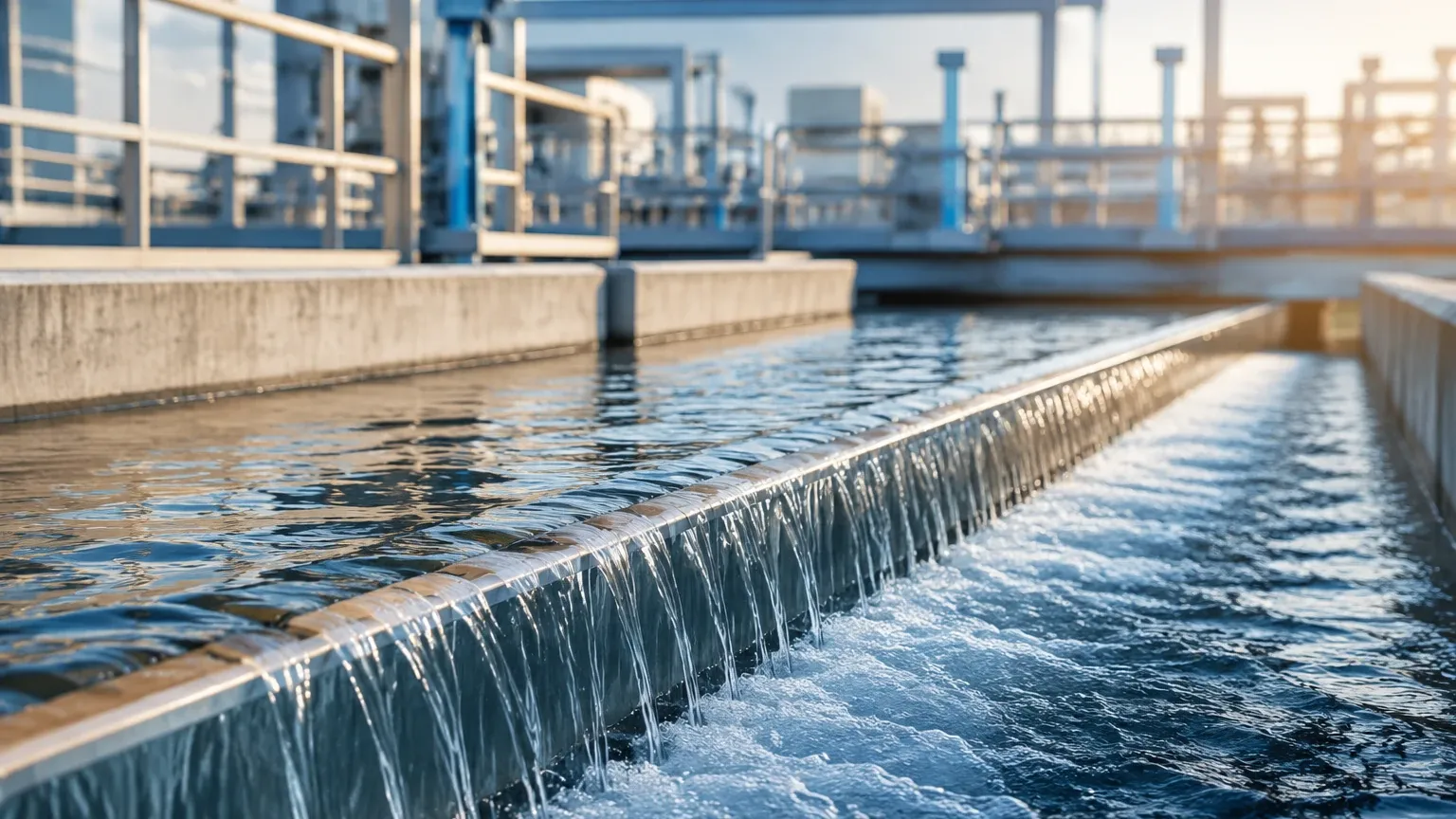
A unique intersection exists between level instrumentation and flow rate meters in open channel applications, such as irrigation canals, wastewater treatment plants, and storm runoff systems. In these environments, the fluid is not contained within a pressurized pipe but flows through a flume or over a weir.
In these scenarios, a level sensor—typically an ultrasonic or radar level meter—is mounted above the channel. By measuring the "head" (the height of the liquid surface) and applying a known mathematical formula specific to the geometry of the flume or weir, the system calculates the flow rate. This method is highly effective for large-scale water management where traditional inline meters would be impractical or too expensive to install. For those integrating such systems, reviewing professional instrumentation options on the Main Page of specialized manufacturers can provide insights into the necessary sensor accuracy and environmental ratings required for these calculations.
Technical Selection Criteria for Flow Instrumentation
Choosing the wrong flow meter can lead to significant measurement errors, increased maintenance costs, and process downtime. Engineers must evaluate several technical parameters during the specification phase:
Fluid Characteristics
- Viscosity: High-viscosity fluids (like heavy oils) may require positive displacement or Coriolis meters, as they can cause significant pressure drops in DP meters.
- Conductivity: Electromagnetic meters require a minimum conductivity (usually >5 μS/cm). They cannot measure hydrocarbons or deionized water.
- Cleanliness: Turbine and DP meters are sensitive to suspended solids, which can erode components or clog pressure ports.
Process Conditions
- Reynolds Number (Re): This dimensionless value determines if the flow is laminar, transitional, or turbulent. Most velocity and vortex meters require turbulent flow (Re > 10,000) to maintain accuracy.
- Turndown Ratio: This is the ratio of the maximum flow to the minimum flow that the meter can accurately measure. If a process varies widely, a meter with a high turndown ratio (e.g., 100:1 for ultrasonic vs. 4:1 for some DP meters) is necessary.
- Pressure and Temperature: Ensure the meter body and seals are rated for the maximum possible process excursions.
Comparison Table of Flow Meter Technologies
| Technology | Typical Accuracy | Turndown Ratio | Fluid Type | Primary Advantage |
| :— | :— | :— | :— | :— |
| Differential Pressure | ±0.5% to ±2% | 4:1 | Liquid, Gas, Steam | Low cost, well-understood |
| Electromagnetic | ±0.25% to ±0.5% | 20:1 to 100:1 | Conductive Liquids | No pressure drop, no moving parts |
| Ultrasonic (Transit-Time) | ±0.5% to ±1% | 50:1 | Clean Liquids | Non-intrusive (clamp-on options) |
| Vortex Shedding | ±1% | 10:1 to 20:1 | Liquid, Gas, Steam | Excellent for high-temp steam |
| Turbine | ±0.25% | 10:1 to 15:1 | Clean Liquids/Gases | High precision and repeatability |
| Coriolis (Mass) | ±0.1% | 100:1 | Liquid, Slurry, Gas | Direct mass measurement |
Installation and Maintenance Best Practices
The accuracy of flow rate meters is heavily dependent on the installation environment. Even the most precise meter will fail if the flow profile is distorted by upstream turbulence.
Straight Pipe Requirements
Most flow meters require a specific length of straight pipe upstream and downstream to allow the flow profile to stabilize. A common rule of thumb is "10D upstream and 5D downstream" (where D is the pipe diameter). If the meter is placed immediately after an elbow, valve, or pump, the resulting swirl and turbulence will cause the meter to over-read or under-read.
Orientation and Grounding
- Liquid Service: Meters should be installed in a low point of the piping or in a vertical line with upward flow to ensure the pipe is always full. Air pockets in a partially filled pipe will cause massive errors in electromagnetic and ultrasonic meters.
- Gas Service: Meters should be installed at high points to prevent condensate from pooling in the sensor.
- Grounding: Electromagnetic meters are sensitive to stray electrical noise. Proper grounding of the fluid to the meter body and the earth is mandatory for stable readings.
Limitations and Application Risks
While modern flow rate meters are highly reliable, they are not "set and forget" devices. Several factors can degrade performance over time:
1. Scaling and Coating: In chemical and wastewater applications, material can build up on the internal walls of the meter or on electrodes. This changes the internal diameter or insulates the sensors, leading to drift.
2. Cavitation: If the pressure drop across a meter is too high, the liquid may flash into vapor (cavitation). This not only destroys measurement accuracy but can physically pit and destroy the meter internals.
3. Entrained Air: In liquid flow, even small percentages of air bubbles can cause ultrasonic signals to scatter or cause turbine meters to over-spin, potentially leading to mechanical failure.
4. Vibration: Vortex and some Coriolis meters are sensitive to pipe vibration. If installed near heavy machinery or pumps without proper support, the mechanical noise can be misinterpreted as flow signals.
Frequently Asked Questions (FAQ)
Q: Can I use an ultrasonic level sensor to measure flow in a pipe?
A: Generally, no. Ultrasonic level sensors are designed for air-to-liquid interfaces. For pipe flow, you need an ultrasonic flow meter that uses transit-time or Doppler sensors specifically designed for pipe mounting.
Q: What is the difference between "Accuracy" and "Repeatability"?
A: Accuracy is how close the meter's reading is to the true value. Repeatability is the meter's ability to provide the same reading under the same conditions. In some control loops, high repeatability is more important than absolute accuracy.
Q: How often should flow rate meters be calibrated?
A: This depends on the industry and the criticality of the measurement. In custody transfer (where money changes hands), calibration may be required annually. In general industrial use, a check every 2-3 years is standard, though self-diagnostic features in modern digital meters can extend these intervals.
Q: Are clamp-on flow meters as accurate as inline meters?
A: Inline meters are typically more accurate because they are factory-calibrated with the specific flow tube. However, modern clamp-on ultrasonic meters are highly effective for surveys and applications where pipe cutting is not possible, often achieving ±1-2% accuracy if installed correctly.
By understanding these principles and constraints, engineering teams can ensure that their flow rate meters provide the reliable data necessary for sophisticated industrial automation and resource management.